
- inCAD Library Home
- > No.000208 Table Lifter
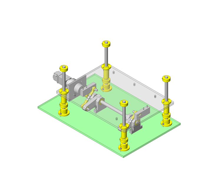
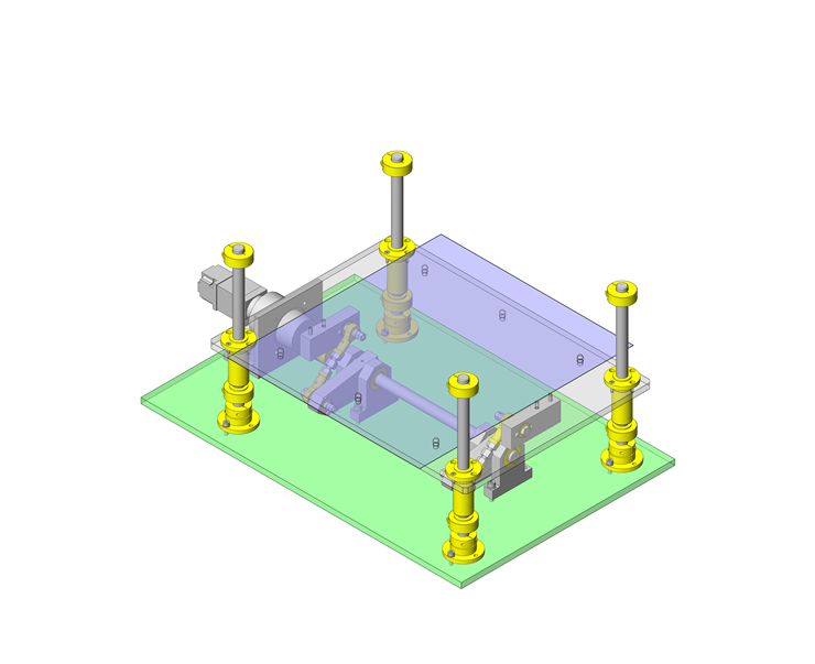
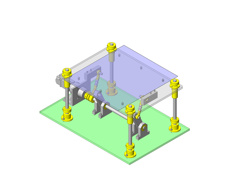
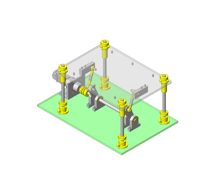
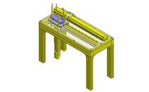
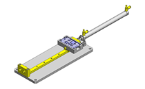
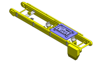
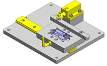
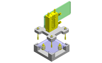
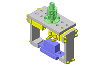
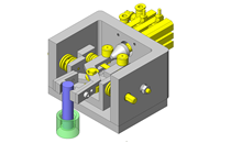
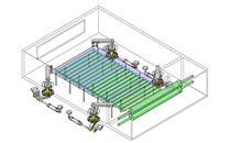
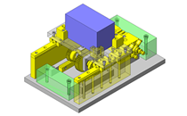
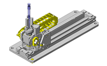
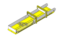
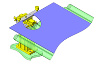
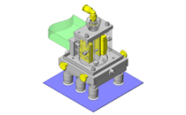
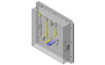
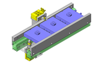
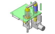
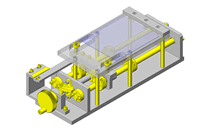
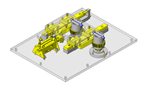
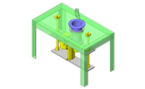
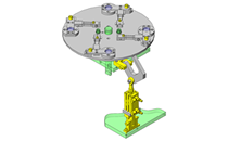
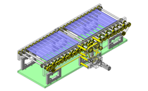
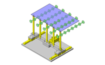
No.000208 Table Lifter
154
A link driven mechanism
Related Category


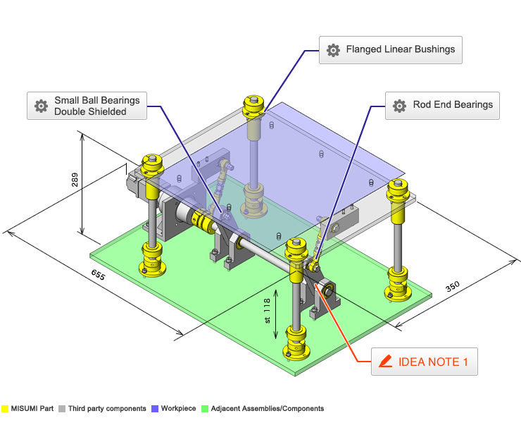
Flanged Linear Bushings
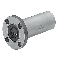
| Product name | Flanged Linear Bushings/Double Type |
|---|---|
| Part number | LHFRWM16G |
| Features | Easy to assemble with bolt-on flanges. The Opposite Counterbored Hole Type is also available. |
Selection criteria
Easy to assemble with bolt-on flanges.
Available sizes
■Flanged Linear Bushings (Double)
| Type | Outer Cylinder | Ball | Retainer | Operating Ambient Temperature | Accessory | ||
|---|---|---|---|---|---|---|---|
| Material | Hardness | Surface Treatment | Material | Material | |||
| Round Flange Square Flange Compact Flange | EN 1.3505 Equiv. | 58HRC- | - | EN 1.3505 Equiv. | Plastic (Duracon M90 equivalent) | -20-80°C | Seal: Material Nitrile Rubber (-20-120°C) |
| Stainless Steel (Stainless Steel) | -20-100°C | ||||||
| Electroless Nickel Plating | EN 1.4125 Equiv. | Plastic (Duracon M90 equivalent) | -20-80°C | ||||
| Stainless Steel (Stainless Steel) | -20-100°C | ||||||
| EN 1.4125 Equiv. | 56HRC- | - | Plastic (Duracon M90 equivalent) | -20-80°C | |||
| Stainless Steel (Stainless Steel) | -20-100°C | ||||||
■Sizes and Dimensions
| I.D. (mm) | Length (mm) |
|---|---|
| 3 | 19 |
| 4 | 23 |
| 5 | 28 |
| 6 | 35 |
| 8 | 45 |
| 10 | 55 |
| 12 | 57 |
| 13 | 61 |
| 16 | 70 |
| 20 | 80 |
| 25 | 112 |
| 30 | 123 |
| 35 | 135 |
| 40 | 151 |
| 50 | 192 |
Selection steps
■Flanged Linear Bushings Selection Steps
- Determine Application Conditions
- (loads, motion pattern, life)
↓
- Temporarily select linear bushing specifications
- (select the shaft diameter, length, and etc. based on the conditions of use.)
↓
- Basic safety check
-
- ●Basic Static Load Rating
- ●Basic Dynamic Load Rating
- ●Allowable Static Moment
- ● Life
↓
- Considerations based on the required performance
- ●Life variations due to various changes (temperature, hardness, etc.)
Accuracy Info
■Accuracy of Flanged Linear Bushings
(mm)
| I.D. | I.D. Tolerance | Height Tolerance from Base Surface |
|---|---|---|
| 3 | 0 -0.010 | ±0.3 |
| 4 | ||
| 5 | ||
| 6 | ||
| 8 | ||
| 10 | ||
| 12 | ||
| 13 | ||
| 16 | ||
| 20 | 0 -0.012 | |
| 25 | ||
| 30 | ||
| 35 | 0 -0.015 | |
| 40 | ||
| 50 |
Performance info.
■Load Information for Flanged Linear Bushings
| I.D. (mm) | Basic Load Rating | |
|---|---|---|
| Basic Dynamic Load Rating (N) | Basic Static Load Rating (N) | |
| 3 | 138 | 210 |
| 4 | 176 | 254 |
| 5 | 263 | 412 |
| 6 | 324 | 529 |
| 8 | 431 | 784 |
| 10 | 588 | 1100 |
| 12 | 657 | 1200 |
| 13 | 813 | 1570 |
| 16 | 1230 | 2350 |
| 20 | 1400 | 2740 |
| 25 | 1560 | 3140 |
| 30 | 2490 | 5490 |
| 35 | 2650 | 6270 |
| 40 | 3430 | 8040 |
| 50 | 6080 | 15900 |
Technical calculations
■Life of Flanged Linear Bushings
When the linear system is in motion with applied load, the rolling surfaces and races are subject to repeated stress, This stress can cause scale-like flaking due to material fatigue. The total run distance until the flaking appears in the "Life" of the linear system.
Rated life can be calculated with the basic dynamic load rating and the actual load applied to the linear bushings, as shown below.
- L: Rated Life (km).
- fH: Hardness Factor (See Fig.1).
- fT: Temperature Factor (See Fig.2).
- fC: Contact Factor (See Table-3).
- fW: Load Factor (See Table-4).
- C: Basic Dynamic Load Rating (N).
- P: Applied Load (N).
●Hardness factor (fH)
For linear applications, the shafts and ball bearings must have sufficient hardness. If they do not, the load rating decreases and the life will be reduced.
Fig. 1. Hardness Factor.
●Temperature factor (fT)
When the temperature of the linear system exceeds 100 degrees C, the hardness will decrease and as a result, the allowable load and life will reduced.
Fig. 2. Temperature Factor.
●Contact factor (fC)
In general, it is common to use two or more bushings on one shaft. In these cases, the load on each bushing will vary depending on the machining precision and will not have equally distributed loads. As a result, the allowable load per bushing will vary depending on the number of bushings used on the shafts. Please compensate the rated life with contact factors on Table-1.
Table-3. Contact Factor.
| Number of Bearings Installed on One Shaft | Contact Factor Fc | |
|---|---|---|
| 1 | 1 | |
| 2 | 0.81 | |
| 3 | 0.72 | |
| 4 | 0.66 | |
| 5 | 0.61 | |
●Load Factor (fW)
To calculate the load applied to the bushings, in addition to the object weight, the inertia force attributed to the motion velocity, moment loads and the variations of each over time must be obtained. However, for reciprocating motion applications, it is difficult to obtain accurate calculations due to the effects of the vibrations and shocks. Therefor, use Table 2 to simplify the life calculations.
| Conditions of Use | fw |
|---|---|
| No external shocks / vibrations, low speed 15m/min or less | 1.0 ~ 1.5 |
| No significant shocks / vibrations, medium speed 60m/min or less | 1.5 ~ 2.0 |
| With external shocks / vibrations, high speed exceeding 60m/min | 2.0 ~ 3.5 |
Life can be obtained by calculating the travel distance per unit of time. When the stroke length and the number of strokes are constant, it can be calculated using the formula below.
- Lh: Life (Hr.).
- L: Rated Life (km).
- Ls: Stroke Length (m).
- n1: Cycles per Minute (cpm).

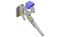
Rod End Bearings
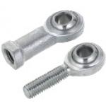
| Product name | Rod End Bearings/Standard |
|---|---|
| Part number | PHSC8 |
Selection criteria
To make the up/down motion smooth by using it as a part of link mechanism.
Available sizes
■Rod End Bearings - Standard
| Type | Material | ||
|---|---|---|---|
| Holder | Spherical Inner Ring | Bushing (Liner) | |
| Steel | EN 1.1181 Equiv.(Trivalent Chromate) | EN 1.3505 Equiv.(58HRC-) | Special Copper Alloy |
| Oil-Free | Bearing I.D. 3/4 (Trivalent Chromate) | EN 1.3505 Equiv.(58HRC-) | Self-lubricating Synthetic Resin |
| Other Than Above | EN 1.3505 Equiv.(58HRC-) | Tetrafluoroethylene resin | |
| Stainless Steel Oil Free | EN 1.4305 Equiv. | EN 1.4125 Equiv.(58HRC-) | Tetrafluoroethylene resin |
■Sizes and Dimensions
| Bearing I.D. | Ball Center - Holder Edge |
|---|---|
| 3 | 12 |
| 4 | 14 |
| 5 | 16 |
| 6 | 18 |
| 8 | 22 |
| 10 | 26 |
| 12 | 30 |
| 14 | 34 |
| 16 | 38 |
| 18 | 42 |
| 20 | 46 |
| 22 | 50 |
Accuracy Info
■Accuracy of Rod End Bearings
| Bearing I.D. | I.D. Tolerance (H7) |
|---|---|
| 3 | +0.009 0 |
| 4 | +0.012 0 |
| 5 | |
| 6 | |
| 8 | +0.015 0 |
| 10 | |
| 12 | +0.018 0 |
| 14 | |
| 16 | |
| 18 | |
| 20 | +0.021 0 |
| 22 |
■Allowable Incline
| Shaft Step Shape | Shaft Condition | Allowable Incline Angle α |
|---|---|---|
| Large | Stepped part of the shaft contacts the outer circumference of the holder. | Small (α1) |
| Medium | Stepped part of the shaft contacts the side or the inner circumference of the holder. | Medium (α2) |
| Not Provided | Shaft contacts the inner circumference of the holder. | Large (α3) |
| Shaft Bore Dia. (mm) | Ball Dia. (mm) | α1(°) | α2(°) | α3(°) | ||||||
|---|---|---|---|---|---|---|---|---|---|---|
| (1) | (2) | (3) | (1) | (2) | (1) | (2) | (1) | (2) | (3) | |
| 3 | - | 9.525 | - | - | 8 | - | 10 | - | 42 | - |
| 4 | - | 10.319 | - | - | 9 | - | 11 | - | 35 | - |
| 5 | 11.112 | 11.112 | 11.91 | 8 | 8 | 13 | 13 | 30 | 30 | 12 |
| 6 | 12.7 | 12.7 | 14.29 | 8 | 8 | 13 | 13 | 30 | 30 | 10 |
| 8 | 15.875 | 15.875 | 17.46 | 8 | 8 | 14 | 14 | 25 | 25 | 12 |
| 10 | 19.05 | 19.05 | 20.64 | 8 | 8 | 14 | 14 | 25 | 25 | 12 |
| 12 | 22.225 | 22.225 | 23.81 | 8 | 8 | 13 | 13 | 25 | 25 | 12 |
| 14 | 25.4 | 25.4 | 26.99 | 10 | 10 | 16 | 16 | 24 | 24 | 14 |
| 16 | 28.575 | 28.575 | 28.58 | 9 | 9 | 15 | 15 | 24 | 24 | 15 |
| 18 | 31.75 | 31.75 | 31.75 | 9 | 9 | 15 | 15 | 24 | 24 | 15 |
| 20 | 34.925 | - | - | 9 | - | 15 | - | 24 | - | |
| 22 | 38.1 | - | - | 10 | - | 15 | - | 23 | - | |
(1) Steel, (2) Oil-free, (3) Stainless Steel Oil-free.
Performance info.
■Static Load Capacity of Rod End Bearings
| Bearing I.D. | Static Load Capacity Radial Ca (kN) | ||
|---|---|---|---|
| Steel | Oil-Free | Stainless Steel Oil Free | |
| 3 | - | 1.57 | - |
| 4 | - | 2.25 | - |
| 5 | 5.59 | 3.92 | 0.98 |
| 6 | 6.86 | 5 | 1.44 |
| 8 | 9.8 | 7.45 | 2.69 |
| 10 | 13.2 | 9.41 | 4.16 |
| 12 | 16.7 | 11 | 5.88 |
| 14 | 20.6 | 15.2 | 6.61 |
| 16 | 25 | 20.2 | 8.33 |
| 18 | 29.4 | 25.2 | 11.52 |
| 20 | 34.3 | 27.8 | - |
| 22 | 41.2 | 35.9 | - |

Small Ball Bearings Double Shielded
| Product name | Small/Deep Groove/Double Shielded |
|---|---|
| Part number | B608ZZ |
Selection criteria
Suitable in limited spaces.
Available sizes
■Small Ball Bearings (Double Shielded)
| Material |
|---|
| EN 1.3505 Equiv. |
■Sizes and Dimensions
| I.D. | O.D. | Thickness |
|---|---|---|
| 2 | 5 | 2.3 |
| 6 | 3.0 | |
| 7 | 3.5 | |
| 2.5 | 6 | 2.6 |
| 7 | 3.5 | |
| 3 | 6 | 2.5 |
| 7 | 3 | |
| 8 | 4 | |
| 9 | 5 | |
| 10 | 4 | |
| 13 | 5 | |
| 4 | 7 | 2.5 |
| 9 | 4 | |
| 11 | ||
| 12 | ||
| 13 | 5 | |
| 16 | ||
| 5 | 8 | 2.5 |
| 11 | 5 | |
| 13 | 4 | |
| 14 | 5 | |
| 16 | ||
| 19 | 6 | |
| 6 | 10 | 3 |
| 13 | 5 | |
| 15 | ||
| 17 | 6 | |
| 19 | ||
| 22 | 7 | |
| 8 | 12 | 3.5 |
| 16 | 5 | |
| 19 | 6 | |
| 22 | 7 | |
| 24 | 8 | |
| 28 | 9 |
Performance info.
■Speed and Load of Small Ball Bearings (Double Shielded)
| I.D. | Basic Load Rating | Allowable Rotational Speed | ||
|---|---|---|---|---|
| O.D. | Cr (Dynamic) N | Cor (Static) N | rpm | |
| 2 | 5 | 169 | 50 | 85000 |
| 6 | 330 | 98 | 75000 | |
| 7 | 385 | 127 | 60000 | |
| 2.5 | 6 | 208 | 74 | 71000 |
| 7 | 385 | 127 | 63000 | |
| 3 | 6 | 208 | 74 | 71000 |
| 7 | 390 | 130 | 63000 | |
| 8 | 560 | 179 | 60000 | |
| 9 | 570 | 187 | 56000 | |
| 10 | 630 | 218 | 50000 | |
| 13 | 1300 | 485 | 40000 | |
| 4 | 7 | 222 | 88 | 60000 |
| 9 | 640 | 224 | 53000 | |
| 11 | 715 | 276 | 48000 | |
| 12 | 957 | 350 | ||
| 13 | 1300 | 485 | 40000 | |
| 16 | 1340 | 523 | 36000 | |
| 5 | 8 | 218 | 131 | 53000 |
| 11 | 715 | 281 | 45000 | |
| 13 | 1080 | 430 | 43000 | |
| 14 | 1330 | 505 | 40000 | |
| 16 | 1730 | 670 | 36000 | |
| 19 | 2336 | 835 | 32000 | |
| 6 | 10 | 495 | 218 | 45000 |
| 13 | 1080 | 440 | 40000 | |
| 15 | 1350 | 530 | ||
| 17 | 2190 | 835 | 38000 | |
| 19 | 2340 | 885 | 32000 | |
| 22 | 3333 | 1423 | 30000 | |
| 8 | 12 | 543 | 274 | 40000 |
| 16 | 1610 | 710 | 36000 | |
| 19 | 1990 | 865 | ||
| 22 | 3350 | 1400 | 34000 | |
| 24 | 4000 | 1590 | 28000 | |
| 28 | 4563 | 1983 | ||


-

-
 Terms of use of CAD data and simplified drawing data
- These terms and conditions (hereinafter referred to as “the Terms") set forth the conditions for downloading CAD data and simplified drawing data provided by MISUMI Corporation (hereinafter referred to as "MISUMI") via www.misumi-europe.com operated by MISUMI Europa GmbH(hereinafter referred to as the "Website"). By downloading CAD data and simplified drawing data posted on the Website (hereafter referred to as “Data”), customers are deemed to have agreed to these Terms.
- 1. Purpose of Use
-
MISUMI offers the following:
1)CAD data found on the Website (3D CAD data, 3D Intermediate data and 2D CAD data) for the purpose of informing customers of the characteristics of the products offered by MISUMI or a manufacturer affiliated with MISUMI for use in their designs.
2)Simplified drawing data (in PDF format) for the purpose of checking the specifications of products. - 2. Characteristics of Data
- There may be a discrepancy in certain characteristics of products (for example: tolerance, surface roughness, chamfer, etc.) between the Data and the actual product. Furthermore, for the purpose of reducing the file size of the Data, some information such as oil groove shapes, threads, or spring shapes, may be removed from the Data.
- 3. Disclaimer
- MISUMI carefully creates the Data but makes no warranty as to the quality, accuracy, functionality, safety, reliability, etc., of the Data. MISUMI may at any time, and with no prior notice to customers, revise or delete Data. MISUMI assumes no responsibility for any damage or loss resulting from any revision or deletion of the Data, or any errors in said data. Customers are solely responsible for all aspects of their own designs, including those made using the Data. MISUMI may provide customers with design example data on the Website, but the quality, accuracy, functionality, safety, reliability, etc., of such data are not guaranteed. MISUMI may, at any time, and in its sole discretion, request that the customer cease its use of or destroy the Data in its possession. MISUMI may request the customer provide MISUMI documentation of such destruction.
- 4.Prohibited Acts
-
Customers or users of the Data, are prohibited from the following acts regarding the Data, in whole or in part:
(1)Requesting quotations or placing orders for products with third parties other than those authorized by MISUMI or its affiliates;
(2)Receiving quotations or orders for products from third parties by providing the Data to a third party or using the Data in their own business;
(3)Displaying links to the Website related to the Data on their own websites, etc., without consent of MISUMI or its affiliates;
(4)Using or reproducing the Data beyond the scope of the above-stated Purpose of Use;
(5)Modifying, altering, tampering with, translating, or adapting the Data;
(6)Selling, transferring, lending, sublicensing, or providing the Data to third parties in any way without consent of MISUMI or its affiliates;
(7)Altering the content, reverse engineering, decompiling, disassembling, or analyzing the Data;
(8)Publicly disclosing or exhibiting the Data without consent of MISUMI or its affiliates;
(9)Using the Data for the purpose of providing products and services identical or similar to those of MISUMI or its affiliates;
(10)Performing acts that interfere with the proper functioning of this Website, such as acquiring Data in bulk. - 5. Copyright
-
All title and copyright in and to any information contained in the Data are owned by MISUMI or the relevant manufacturer affiliated with MISUMI and are protected by applicable copyright laws and international treaties. By downloading Data, the customer acquires no ownership rights of any kind in the intellectual property contained within. Without prior approval from MISUMI, no part of the Data may be utilized (reproduced, modified, reverse-engineered, uploaded, presented, sent, distributed, licensed, sold, or published) for any purpose other than that mentioned above.
In the event Data is found to have been to be used for any purpose other than that mentioned above or against any applicable laws or the Terms, MISUMI may pursue any legal remedy available to it, which may result in forbidding the offending user from using the Data or accessing the Website. - 6. Third-Party Data
- MISUMI offers some Data provided by third parties. Such Data may be subject to separate terms and conditions, in addition to these terms. MISUMI makes no guarantee or warranty regarding Data from third parties.
- 7. Export Control
- Customers shall comply with all applicable laws and regulations regarding the export of the Data.
- 8. Amendments to the Terms
- MISUMI may, at any time, and in its sole discretion, modify these terms and conditions; any such modification will be effective immediately.
- 9. Severability
- If any term or provision of these Terms is invalid, illegal, or unenforceable in any jurisdiction, such invalidity, illegality, or unenforceability shall not affect any other term or provision of these Terms or invalidate or render unenforceable such term or provision in any other jurisdiction. Section 139 BGB (German Civil Code) shall not apply.
- 10.Miscellaneous
-
In the event that Customers violate the Terms, MISUMI and/or MISUMI Europa GmbH shall be entitled to claim the damages and expenses (including attorney's fees) incurred by such violation against the Customers.
These Terms and any disputes arising in connection therewith shall be exclusively governed by and construed in accordance with the laws of the Federal Republic of Germany, without regard to its conflicts of law principles. The courts located in Frankfurt am Main/Germany shall have exclusive jurisdiction to adjudicate any dispute arising in connection with these Terms. By downloading the Data, you agree to submit to the exclusive and personal jurisdiction of the courts located in Frankfurt am Main/Germany. - Revised: September 21, 2025
CAD Data Download (Unit Assembly)
CAD Data Download: File Format
Cautions on the CAD data
-
Assembly data shows the assembly drawings in the concept design phase. The sole purpose of the data is to explain the structure and functionality of the assembly and is not considered nor to be used as a final design.
You will need to edit the Data so that it meets your specific design conditions. -
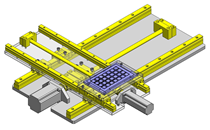
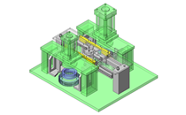
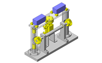
The CAD data unit assembly consists of sub-assemblies.
Each sub-assembly unit can be used as it is or can be edited. - The Data for fabricated parts is based on easy-to-edit dimensions and shapes in sketches and histories.
- The Data including the third-part components are made by the Company.
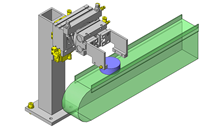
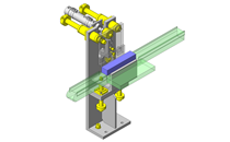
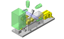
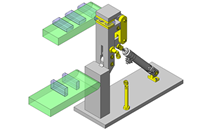
* The part in the frame is a sub-assembly unit.
-

- * Unit assembly CAD data consists of some sub-assemblies.
Each sub-assembly unit can be used as it is or can be edited.
Application Overview
Purpose
- Purpose
- To lift workpieces and feed them to the next process.
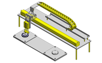
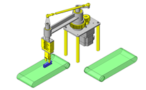
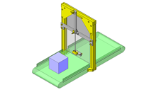
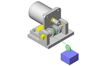
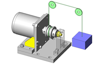
- Operation
- The workpieces are fed from the previous process by a robot arm.
The lifter lifts up and stops at an appropriate height level of the next feeding machine.
- The workpieces are fed from the previous process by a robot arm.
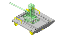
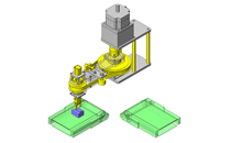
Points for use
- Class 100 Transfer of glass substrates in a clean room that is controlled in accordance with Class 100 requirements.
Target workpiece
- Shape: Glass substrate
- Size: t0.5 x W350 x D360mm
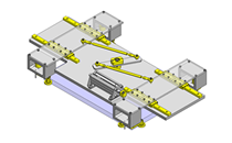
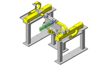
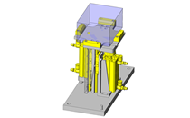
Design Specifications
Operating Conditions or Design Requirements
- Lifter stroke: 118mm
- External dimensions: W655 x D350 x H289mm
Required Performance
- Load: Workpiece+base = 35N
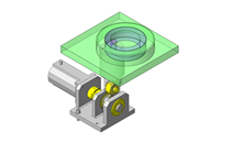
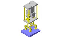
Selection Criteria for Main Components
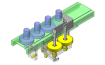
- Select a servo motor that can lift the load 35N at a speed of 5mm/s.
Design Evaluation
Verification of main components
- Select a motor that satisfies the load inertia and load torque.
- Calculation of the load inertia applied to the motor shaft.
- Conditions (values): Reducer Inertia JMG = 0.041kg・cm², brake inertia JMB = 0.006kg・cm², coupling inertia JC = 0.728kg・cm², other output shafts inertia JO = 5.000kg・cm², sprocket inertia JZ = 7.658kg・cm², movable unit inertia JF2 = 0.290kg・cm², reduction ratio = 1/nm = 25/484.
- The load inertia applied to the shaft, JL, is expressed by JL = JMG + JMB + JF2 + (JC + JO + JZ) x (1/nm)2 (JL = 0.041 + 0.006 + 0.290 + (0.728 + 5 + 7.658) x (25/484)² = 0.373kg・cm²).
- The inertia ratio, m, is expressed by m = JL/JM (m = 0.373/0.078 = 4.8 < 17 times (motor specification recommendation value)).
- Servo motor moment of inertia, JM, is 0.078kg・cm² (according to the catalog).
- Torque calculation in lifting and acceleration
- Conditions (values): Drive efficiency η = 0.700, motor rotation speed No = 369.748r/min, acceleration time Tsa = 0.693s, load torque applied to the motor shaft TL = 0.064N・m
- Torque TMa in lifting and acceleration is expressed by TMa = ((((JL/η) + JM) x No)/(9.55 x 104 x Tsa)) + TL (TMa = ((((0.373/0.7) + 0.078) x 369.748)/(9.55 x 104 x 0.693)) + 0.064 = 0.067N・m)
- The torque reaches its peak in lifting and acceleration. Since the rated torque is Ttyp = 0.32N・m, the peak load ratio Rp is expressed by Rp = (Tma/Ttyp) x 100 (Rp = (0.067/0.32) x 100 = 20.94%)
- When the effective load torque is derived from the torques in each operation pattern, the rated torque becomes 0.064N・m < 0.32N・m
Other Design Consideration
- Motor is mounted below the workpiece unit to avoid dust contamination generated by the motor.
Explore Similar Application Examples


Payment Method


On-Demand Manufacturing
Certificates


Copyright © MISUMI Corporation All Rights Reserved.