- inCAD Library Home
- > No.000150 90° Rotational transfer mechanism
No.000150 90° Rotational transfer mechanism
65
65
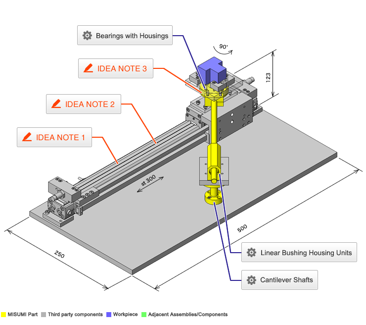
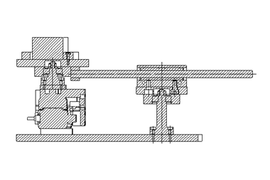
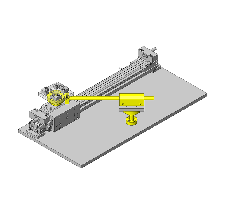
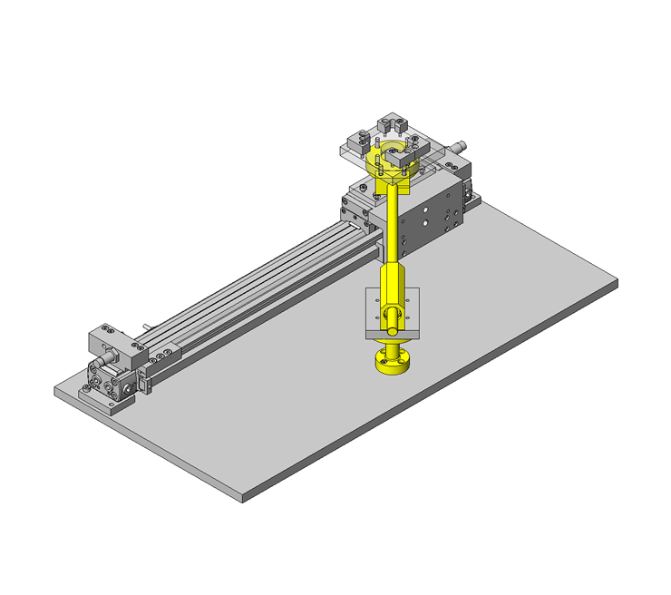
Rotate workpiece 90 degrees while transporting
Related Category
- * Unit assembly CAD data consists of some sub-assemblies.
Each sub-assembly unit can be used as it is or can be edited.
Application Overview
Purpose
- Transfer and rotate a workpiece simultaneously.
Target workpiece
- Shape: Connector
- Size: W40 x D40 x H30mm
- Weight: 150g
Design Specifications
Operating Conditions or Design Requirements
- Horizontal movement stroke: 300mm
- Rotation angle: 90°
- External dimensions: W500 x D250 x H123mm
Required Performance
- Positioning accuracy: ±0.1 / 300mm
- Angle: 90° ±0.05°
Selection Criteria for Main Components
- Ensure that the cylinder with shock absorbing stopper can provide the required positioning accuracy.
Design Evaluation
Verification of main components
- Verify that the cylinder thrust and shock absorber meet the design requirements.
- Conditional values: Friction coefficient of the guide on the rod-less cylinder µ = 0.01, air cylinder efficiency η = 0.82, mass of moving part = 1.6kg, workpiece mass = 150g
- Ø20 cylinder thrust: Fs = 157N at applied pressure of 0.5MPa
- Cylinder thrust necessary to transfer a workpiece F = (0.15 + 1.6) x 0.01 x 9.806 / 0.82 = 0.21N < 157N = Fs
⇒Sufficiently satisfied.
Check the shock absorber capacity. - Conditional values: Stroke of the shock absorber with these specifications St = 8mm, maximum absorbed energy Ea = 7J, Equiv. mass of the colliding object Me = 18kg [atV = 0.5 m/s]
- Check the absorbable kinetic energy.
E = 1 / 2 x m ・ V2 + Fs x St = 1 / 2 x (0.15 + 1.6) x 0.52 + 157 x 0.008 = 1.47J
Ea / 2 = 7J / 2 = 3.5 > 1.47J
⇒One half or less of the maximum absorbable energy. Thus the kinetic energy can be absorbed. - Check the absorbable equivalent mass of the colliding object.
Me = m+2 ・ Fs ・ St / V2 = (0.15 + 1.6) + 2 x 157 x 0.008 / 0.52 = 6.774kg < Me = 18kg
⇒Can be absorbed.
Other Design Consideration
- A cylinder with high mechanical rigidity is selected to meet the requirements for positional accuracy.
Explore Similar Application Examples
Page
-
/
-


