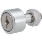
Precision Pivot Pins
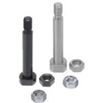
Product name | Precision Pivot Pins/Flanged/Threaded with Lock Nut |
Part number | PCLBGHNU5-40 |
* Orange colored cells in the table below indicate the part numbers used in this example.
Selection criteria
Suitable for oscillation fulcrum to hold down the workpiece.
Back to page top
Available sizes
■Pivot pin (Lock nut with shoulder, L configurable type)
Nut | Material | Hardness | Surface Treatment |
Standard nut U-nut | EN 1.1191 Equiv. | - | Black Oxide |
40 - 45HRC |
- | Electroless Nickel Plating |
40 - 45HRC |
Plating Hardness: 750HV - | Hard Chrome Plating: Plating Thickness 3µm or more |
EN 1.4301 Equiv. | - | - |
EN 1.4125 Equiv. | 45 - 50HRC |
■Sizes and Dimensions
Pin Dia. (mm) | Length (mm) 0.1mm Increment | Screw Dia. (Coarse) |
4 | 5.0 - 50.0 | M3 |
5 | 5.0 - 60.0 | M4 |
6 | 10.0 - 100.0 | M5 |
8 | M6 |
10 | M8 |
12 | 15.0 - 200.0 | M10 |
13 | 20.0 - 200.0 | M12 |
14 |
15 |
16 | 20.0 - 200.0 |
17 |
18 |
20 | M16 |
22 |
25 |
30 | 40.0 - 200.0 |
Back to page top
Accuracy Info
■Accuracy information of pivot pin
■Pin Dia. Tolerance:
Pin Dia. Tolerance (g6) |
4 - 6 | - 0.004 - 0.012 |
8 ・ 10 | - 0.005 - 0.014 |
12 - 18 | - 0.006 - 0.017 |
20 - 30 | - 0.007 - 0.020 |
Back to page top
Air Linear Guides
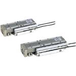
Product name | Air Linear Guides/MPPTU12 Series |
Part number | MPPU12-45-SS |
* Orange colored cells in the table below indicate the part numbers used in this example.
Selection criteria
Handy as Drive Source requiring no guidance.
Back to page top
Available sizes
■Pneumatically driven linear guides
I.D. of Cylinder | Horizontal (mm) | Vertical (mm) | Thickness (mm) | Stroke Length (mm) |
Ø10 | 27 | 70 | 20 | 15 |
85 | 30 |
100 | 45 |
Ø12 | 32 | 76.5 | 22 | 20 |
86.6 | 30 |
101.6 | 45 |
116.6 | 60 |
Back to page top
Selection steps
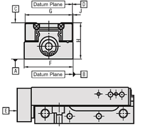
■Accuracy Information of Pneumatically Driven Linear Guides
Unit: mm
Bore Dia. | Ø10 | Ø12 |
Stroke | 15 / 30 / 45 | 20 / 30 / 45 | 60 |
Parallelism | Plane C to Plane A | 0.02 | 0.02 |
Plane D to Plane B | 0.02 | 0.02 |
Running parallelism | Plane C to Plane A | 0.004 | 0.004 | 0.006 |
Plane D to Plane B | 0.004 | 0.004 | 0.006 |
Squareness | Plane E to Plane A | 0.15 | 0.15 |
Plane E to Plane B | 0.15 | 0.15 |
J Dimension Tolerance | ±0.025 | ±0.025 |
F Dimension Tolerance | ±0.2 | ±0.2 |
G Dimension Tolerance | ±0.2 | ±0.2 |
H Dimension Tolerance | ±0.05 | ±0.05 |
Back to page top
Performance info.
■Performance info. of Pneumatically Driven Linear Guides
■Operating Pressure Range
Min. Operating Pressure (MPa): 0.15
Max. Operating Pressure (MPa): 0.70
Pressure Resistance (Mpa): 1.05
■Theoretical Thrust
Unit: N
Tube I.D. | Operation Direction | Rod Dia. (mm) | Operating Pressure (MPa) |
0.4 | 0.5 |
Ø10 | Outstroke | Ø4 | 31 | 39 |
Instroke | 26 | 33 |
Ø12 | Outstroke | Ø5 | 45 | 57 |
Instroke | 37 | 47 |
■Allowable Load Moment
Stroke (mm) | Allowable Load Moment N・m |
Pitching | Yawing | Rolling |
15 / 30 / 45 | 1.8 | 2.0 | 1.9 |
20 / 30 / 45 / 60 | 3.0 | 3.4 | 3.8 |
Back to page top
Cam Follower
Product name | Cam Followers/Flat Type/No Seal |
Part number | CFFRS5-13 |
* Orange colored cells in the table below indicate the part numbers used in this example.
Selection criteria
Popular as lever holder.
Back to page top
Available sizes
■Cam follower (Flat type)
Grease | Seal | Material | Accessory |
Not Provided | Provided |
General | ○ | ○ | EN 1.3505 Equiv. | 1 Hex Nut (EN 1.1191 Equiv. Iron Oxide Black Coating) |
○ | ○ | EN 1.4125 Equiv. | Hex Nut 1pc. (EN 1.4301 Equiv. ) |
Low Dust Generation | - | ○ |
■Sizes and Dimensions
Shaft DIA. (mm) | Outer Ring DIA. (mm) |
5 | 13 |
6 | 16 |
8 | 19 |
10 | 22 |
26 |
12 | 30 |
32 |
16 | 35 |
18 | 40 |
20 | 52 |
Back to page top
Accuracy Info
■Accuracy Information of Cam Followers
■Shaft Dia. Tolerance
Shaft DIA. (mm) | h7 Tolerance |
5 | 0 - 0.012 |
6 |
8 | 0 - 0.015 |
10 |
12 | 0 - 0.018 |
16 |
18 |
20 | 0 - 0.021 |
■Outer Race Dia. Tolerance
Outer Ring DIA. (mm) | Tolerance |
13 ・ 16 | 0 - 0.008 |
19 - 30 | 0 - 0.009 |
32 - 40 | 0 - 0.011 |
52 | 0 - 0.013 |
Back to page top
Performance info.
■Speeds・Loads (Load info.) of cam followers
Shaft Dia. - Outer Ring Dia. (mm) | Basic Dynamic Load Rating (kN) | Basic Static Load Rating (kN) | Max. Allowable Load (kN) | Max. Rotational Speed (rpm) |
With Seal | No Seal |
3 - 10 | 1.47 | 1.18 | 0.36 | 32900 | 47000 |
4 - 12 | 2.06 | 2.05 | 0.78 | 25900 | 37000 |
5 - 13 | 3.14 | 2.77 | 1.42 | 20300 | 29000 |
6 - 16 | 3.59 | 3.58 | 2.11 | 17500 | 25000 |
8 - 19 | 4.17 | 4.65 | 4.73 | 14000 | 20000 |
10 - 22 | 5.33 | 6.78 | 5.81 | 11900 | 17000 |
10 - 26 |
12 - 30 | 7.87 | 9.79 | 9.37 | 9800 | 14000 |
12 - 32 |
16 - 35 | 12.0 | 18.30 | 17.30 | 7000 | 10000 |
18 - 40 | 14.7 | 25.2 | 26.1 | 5950 | 8500 |
20 - 52 | 20.7 | 34.8 | 32.1 | 4900 | 7000 |
Back to page top
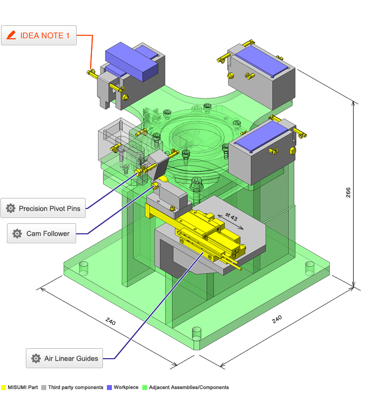
IDEA NOTE The workpiece is always clamped by the spring. In the discharge of a charged workpiece, it is unclamped by a pusher
The workpiece being clamped by the spring is unclamped as the cylinder presses the pusher against the hinge block to incline the hinge to the center.