Tłumaczymy nasz sklep na język polski!
- Stroke(mm)
- 1,000
- 1,005
- 1,050
- 1,100
- 1,200
- 1,300
- 1,500
- 1,580
- 1,700
- 1,800
- 1,900
- 2,000
- 2,500
- 3,000
- 4,000
- 5,000
- 50
- 60
- 75
- 100
- 110
- 115
- 120
- 124
- 125
- 126
- 130
- 135
- 140
- 145
- 150
- 155
- 160
- 165
- 170
- 175
- 180
- 185
- 190
- 200
- 205
- 210
- 215
- 220
- 225
- 230
- 235
- 240
- 245
- 250
- 255
- 260
- 265
- 270
- 275
- 280
- 290
- 300
- 310
- 315
- 320
- 325
- 330
- 335
- 340
- 350
- 360
- 365
- 370
- 375
- 380
- 385
- 390
- 400
- 405
- 410
- 415
- 420
- 425
- 430
- 435
- 440
- 445
- 450
- 460
- 470
- 475
- 480
- 490
- 500
- 510
- 520
- 525
- 530
- 540
- 550
- 560
- 570
- 575
- 580
- 600
- 610
- 620
- 625
- 630
- 640
- 645
- 650
- 660
- 665
- 670
- 675
- 680
- 682
- 700
- 710
- 715
- 720
- 725
- 730
- 740
- 750
- 760
- 770
- 780
- 790
- 800
- 805
- 820
- 830
- 850
- 860
- 870
- 875
- 880
- 890
- 900
- 910
- 920
- 930
- 940
- 950
- 960
- 995
- 1010
- 1020
- 1040
- 1060
- 1110
- 1150
- 1160
- 1170
- 1210
- 1230
- 1250
- 1270
- 1280
- 1320
- 1330
- 1340
- 1350
- 1380
- 1390
- 1400
- 1430
- 1440
- 1450
- 1460
- 1470
- 1510
- 1550
- 1600
- 1640
- 1650
- 1660
- 1680
- 1750
- 1780
- 1785
- 1810
- 1839
- 1844
- 1850
- 1860
- 1920
- 1950
- 2100
- 2200
- 2300
- 2400
- 3500
- Max. Load Mass(kg)
- 18
- 25
- 35
- 49
- 68
- 93
- 130
- Table Size Length L(mm)
- 80
- 100
- 102
- 132
- 162
- 200
- 230
- Cylinder Inner Diameter(Ø)
- 16
- 20
- 25
- 32
- 40
- 50
- 63
- Table Size Width W(mm)
- 58
- 68
- 70
- 72
- 84
- 102
- 118
- 144
- 168
- Table Size Height H(mm)
- 40
- 46
- 54
- 68
- 84
- 107
- 130
- Operating Pressure(MPa)
- Piping Format
- Custom-made Specifications
- 0.5
- 3
- 5
- End Block
- Model
- 1
- 2
- 3
- 4
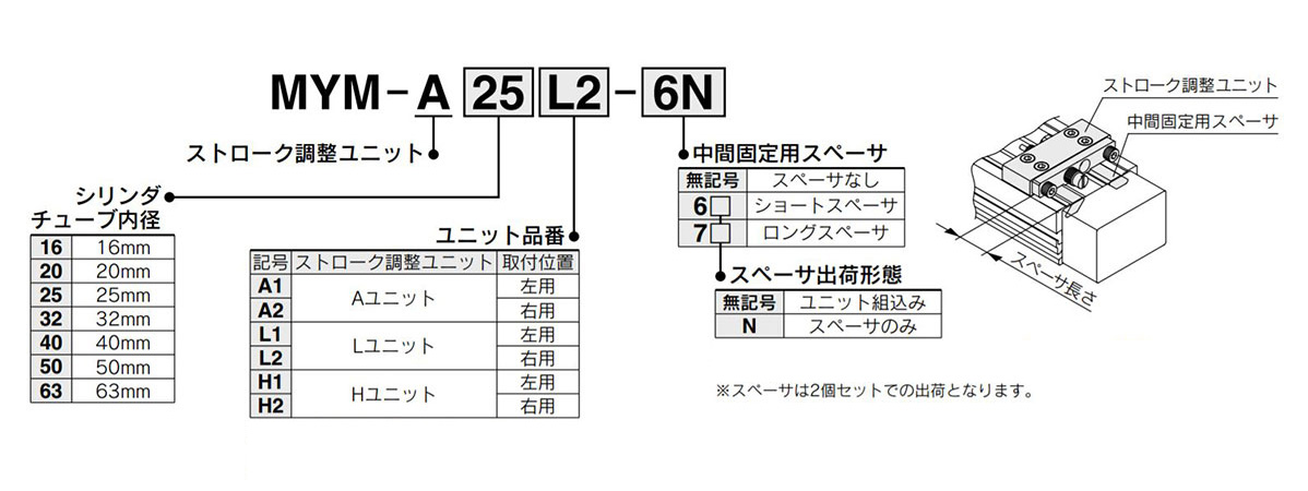
- Stroke Adjustment Unit Symbol
- Type
- Type
- CAD
- 2D
- 3D
- Szacowane dni wysyłki
- Wszystko
- W ciągu 4 dni robocze
- W ciągu 7 dni robocze
- W ciągu 8 dni robocze
- W ciągu 12 dni robocze
- W ciągu 24 dni robocze
- W ciągu 28 dni robocze
- W ciągu 33 dni robocze
- W ciągu 38 dni robocze
- W ciągu 47 dni robocze
- W ciągu 98 dni robocze
MY1C, Mechanical Joint Rodless Cylinder, Cam Follower Guide w / o Stroke Adjustment

Przestroga
- Product pictures are representations. CAD data is not supported by some of the model numbers.
Numer części:
.Informacje o produkcie
Drawing
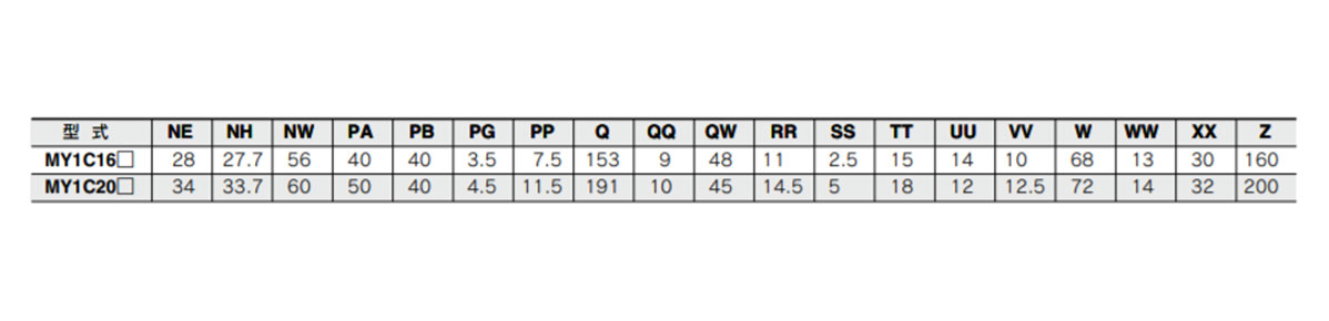
Standard type / centralized piping type ⌀16 (cylinder inner diameter 16 mm) ⌀20 (Cylinder inner diameter 20 mm)
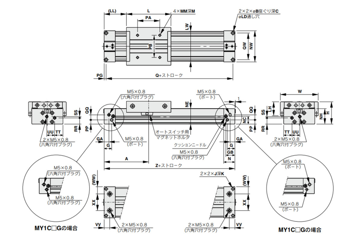
MY1C16□ / MY1C20□-stroke
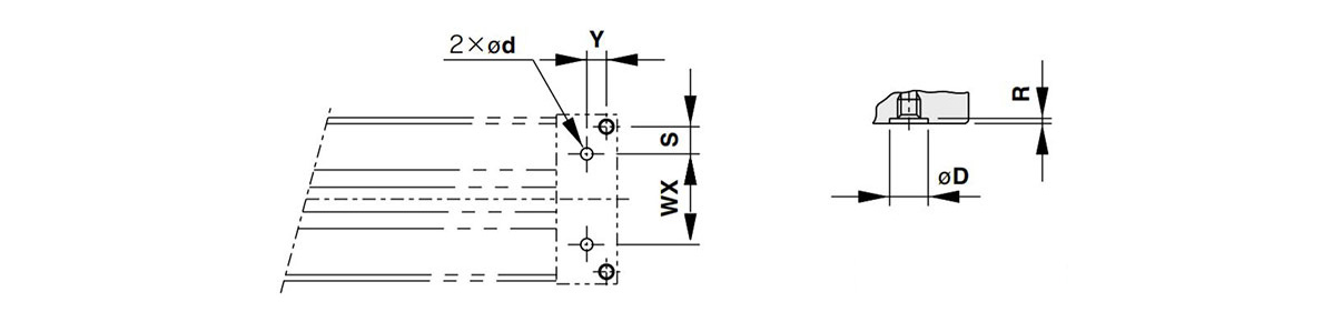
Piping hole for centralized piping on the bottom of MY1C16□ / MY1C20□ (right: piping on the bottom (applicable O-ring))
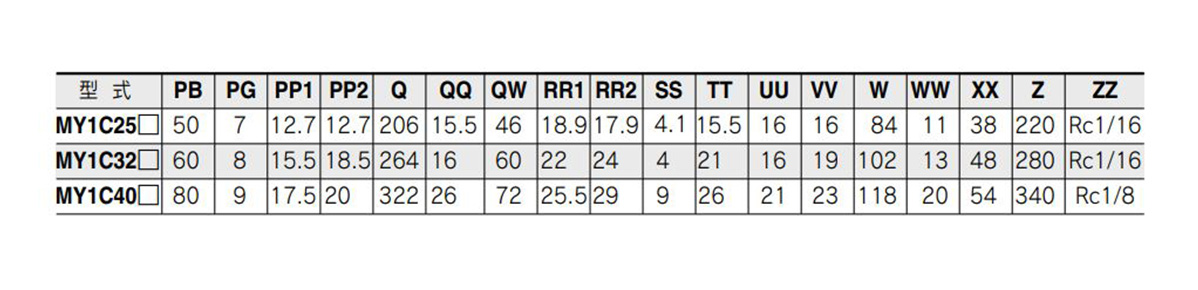
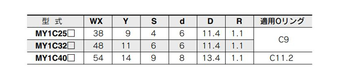
Standard type / centralized piping type ⌀25 (cylinder inner diameter 25 mm) ⌀32 (cylinder inner diameter 32 mm), ⌀40 (Cylinder inner diameter 40 mm)
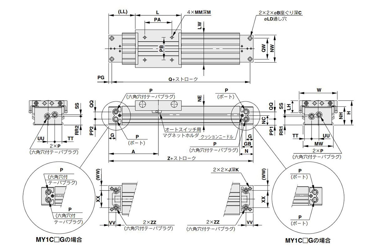
MY1C25□ / MY1C2532□ / MY1C2540□-stroke

Piping hole for centralized piping on the bottom of MY1C25□ / MY1C2532□ / MY1C2540□ (right: bottom side (ZZ part) piping part (applicable O-ring))
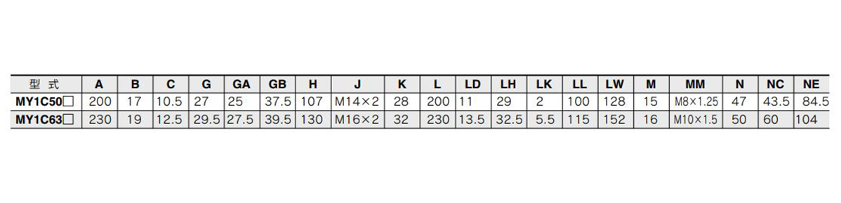
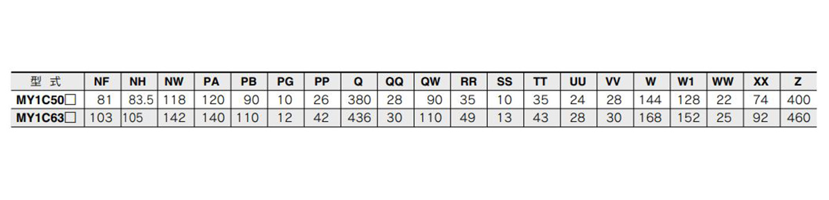
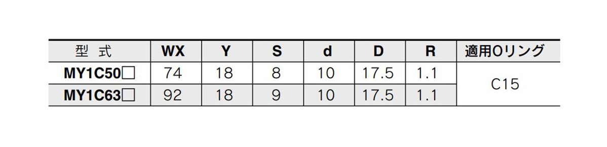
Standard type / centralized piping type ⌀50 (cylinder inner diameter 50 mm) ⌀63 (Cylinder inner diameter 63 mm)
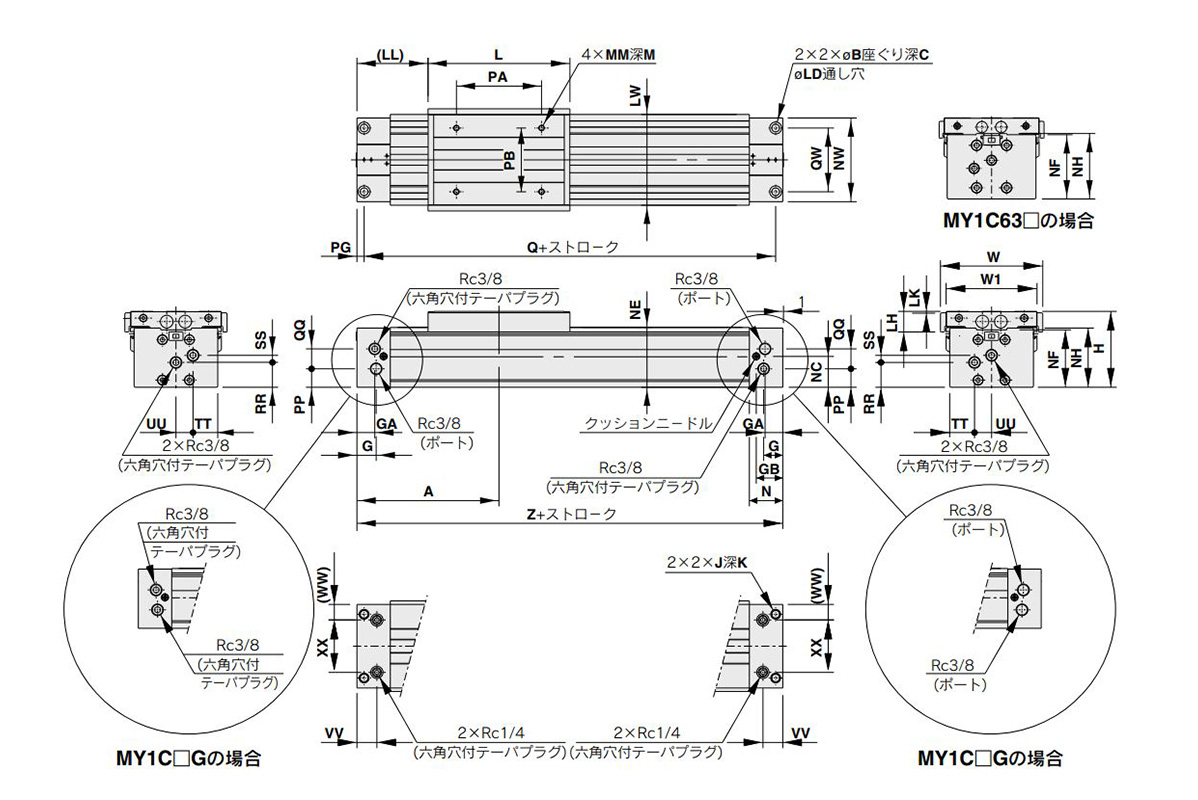
MY1C50□ / MY1C5063□ stroke
Piping hole for centralized piping on the bottom of MY1C50□ / MY1C5063□ (right: bottom side (ZZ part) piping part (applicable O-ring))
Product Specifications
Standard Specifications
| Tube Inner Diameter (mm) | 16 | 20 | 25 | 32 | 40 | 50 | 63 | |
|---|---|---|---|---|---|---|---|---|
| Fluid | Air | |||||||
| Operation Type | Double-acting type | |||||||
| Operating Pressure Range | 0.15 to 0.8 MPa | 0.1 to 0.8 MPa | ||||||
| Proof Pressure | 1.2 MPa | |||||||
| Ambient and fluid temperature | 5 to 60°C | |||||||
| Cushioning | Air cushion | |||||||
| Lubrication | Not required | |||||||
| Stroke Length Tolerance | 1,000 or less (0 to +1.8) 1,001 to 3,000 (0 to +2.8) | 2,700 or less (0 to +1.8), 2,701 to 5,000 (0 to +2.8) | ||||||
| Piping Connection Port Diameter | Front/side port | M5 × 0.8 | Rc 1/8 | Rc 1/4 | Rc 3/8 | |||
| Bottom port | ⌀4 (Connection diameter 4 mm) | ⌀6 (Connection diameter 6 mm) | ⌀8 (Connection diameter 8 mm) | ⌀10 (Connection diameter 10 mm) | ||||
Piston Speed
| Tube Inner Diameter (mm) | 16 to 63 | |
|---|---|---|
| No stroke adjustment unit | 100 to 1,000 mm/s | |
| Stroke adjustment unit | A unit | Note1) 100 to 1,000 mm/s |
| L unit, H unit | Note2) 100 to 1,500 mm/s | |
Note 1) please note that the capacity of the air cushion will decrease as the stroke adjustment allowance by the adjust bolt increases. Meanwhile, in ranges exceeding the air cushion stroke, the working piston speed will become 100 to 200 mm/s.
Note 2: The working piston speed will become 100 to 1,000 mm/s when using centralized piping.
Note 3: Use at a speed within the range of the absorption capacity. See digital catalog.
Theoretical Output Table
(Unit: N)
| Tube Inner diameter (mm) | Pressure received Area (mm2) | Operating Pressure (MPa) | ||||||
|---|---|---|---|---|---|---|---|---|
| 0.2 | 0.3 | 0.4 | 0.5 | 0.6 | 0.7 | 0.8 | ||
| 16 | 200 | 40 | 60 | 80 | 100 | 120 | 140 | 160 |
| 20 | 314 | 62 | 94 | 125 | 157 | 188 | 219 | 251 |
| 25 | 490 | 98 | 147 | 196 | 245 | 294 | 343 | 392 |
| 32 | 804 | 161 | 241 | 322 | 402 | 483 | 563 | 643 |
| 40 | 1,256 | 251 | 377 | 502 | 628 | 754 | 879 | 1,005 |
| 50 | 1,962 | 392 | 588 | 784 | 981 | 1,177 | 1,373 | 1,569 |
| 63 | 3,115 | 623 | 934 | 1,246 | 1,557 | 1,869 | 2,180 | 2,492 |
Note) theoretical output (N) = pressure (MPa) x pressure receiving area (mm2).
Weight Table
(Unit: kg)
| Tube Inner diameter (mm) | Basic Weight | Extra weight Extra mass per hit | Movable Part Weight | Side support Bracket weight (Per pair) | Stroke adjustment unit weight (Per unit) | ||
|---|---|---|---|---|---|---|---|
| A/B type | A unit Weight | L unit Weight | H unit Weight | ||||
| 16 | 0.67 | 0.12 | 0.22 | 0.01 | 0.03 | 0.04 | — |
| 20 | 1.06 | 0.15 | 0.31 | 0.02 | 0.04 | 0.05 | 0.08 |
| 25 | 1.58 | 0.24 | 0.41 | 0.02 | 0.07 | 0.11 | 0.18 |
| 32 | 3.14 | 0.37 | 0.86 | 0.04 | 0.14 | 0.23 | 0.39 |
| 40 | 5.60 | 0.52 | 1.49 | 0.08 | 0.25 | 0.34 | 0.48 |
| 50 | 10.14 | 0.76 | 2.59 | 0.08 | 0.36 | 0.51 | 3.38 |
| 63 | 16.67 | 1.10 | 4.26 | 0.17 | 0.68 | 0.83 | 1.08 |
Calculation method/example: MY1C25-300A
- Basic weight: 1.58 kg
- Extra weight: 0.24/50st
- A unit weight: 0.07 kg
- Cylinder Stroke: 300st
1.58 + 0.24 × 300 ÷ 50 + 0.07 × 2≒3.16 kg
Structural Drawing
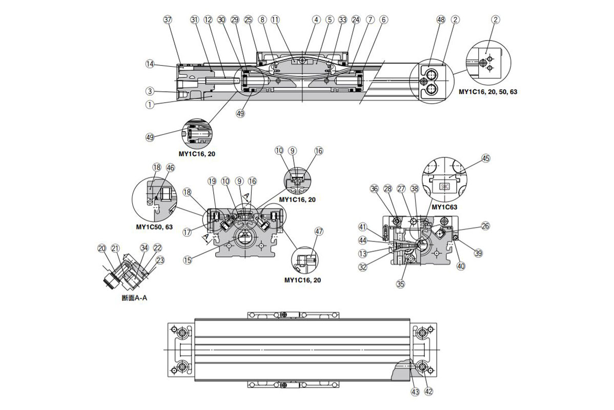
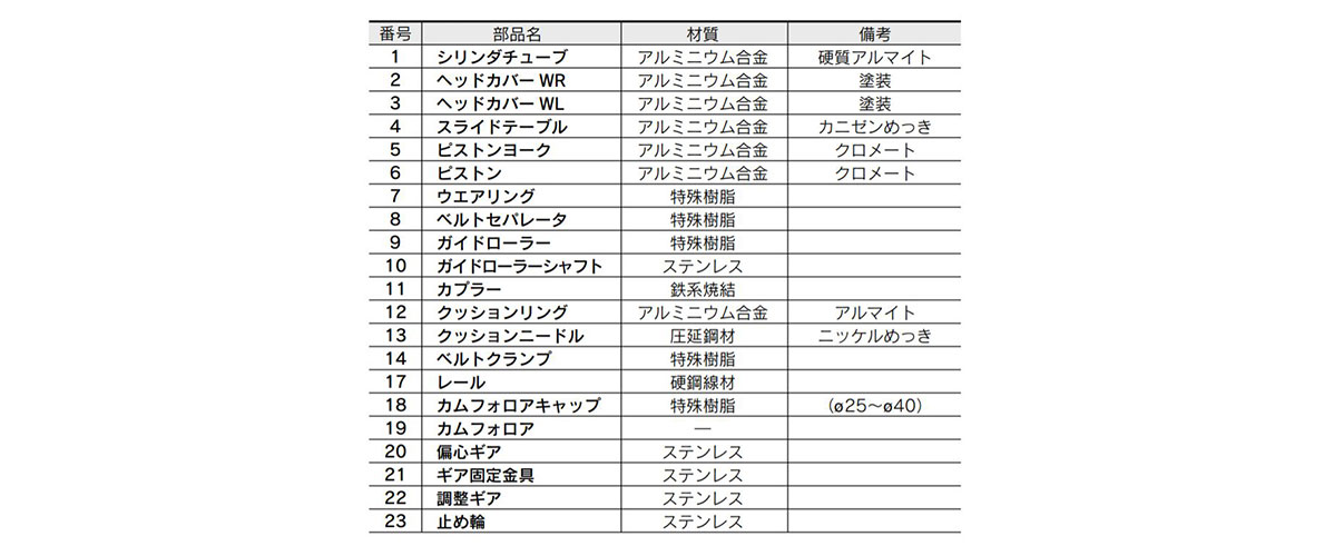
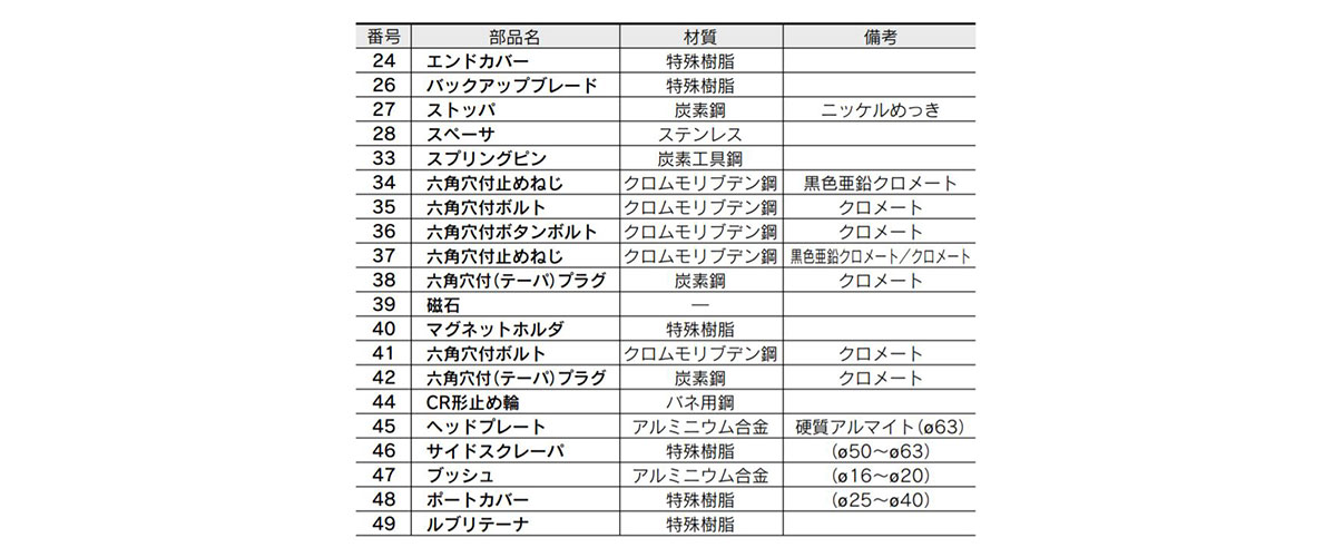
Component parts table image
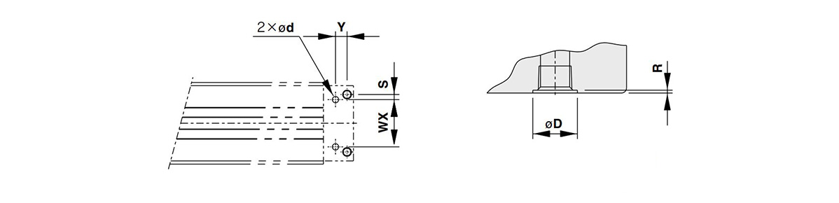
Specification Table
Standard type / centralized piping type ⌀16 (cylinder inner diameter 16 mm) ⌀20 (Cylinder inner diameter 20 mm)
MY1C16□ / MY1C20□
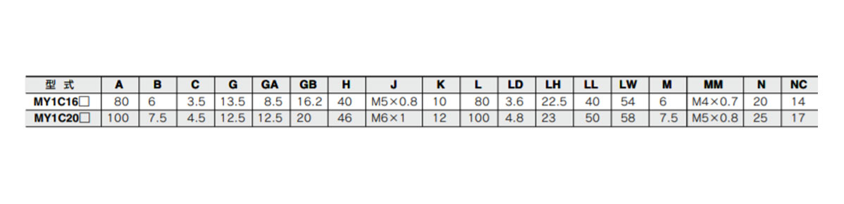
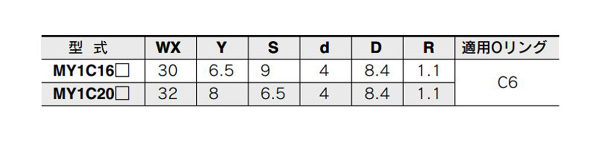
Piping hole for bottom centralized piping
* Please process the mounting surface with these dimensions.
Standard type / centralized piping type ⌀25 (cylinder inner diameter 25 mm) ⌀32 (cylinder inner diameter 32 mm), ⌀40 (Cylinder inner diameter 40 mm)
MY1C25□ / MY1C32□ / MY1C40□
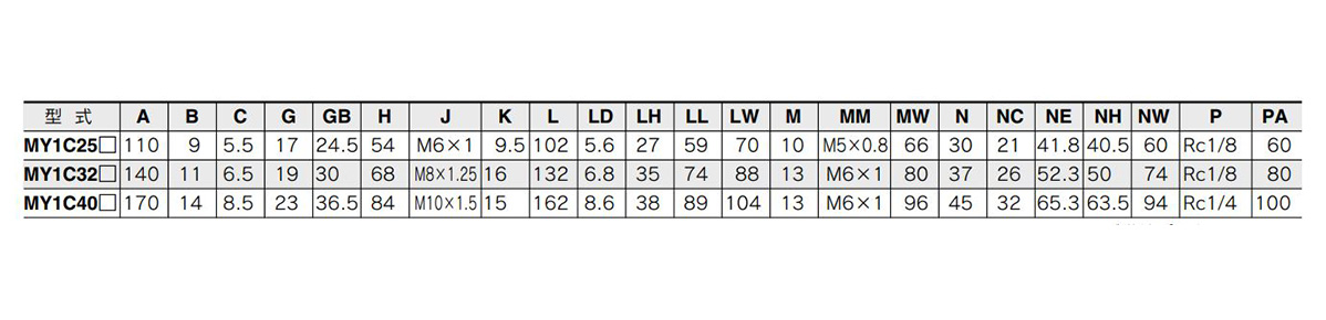
* P indicates the cylinder supply port.
Piping hole for bottom centralized piping
* Please process the mounting surface with these dimensions.
Standard type / centralized piping type ⌀50 (cylinder inner diameter 50 mm) ⌀63 (Cylinder inner diameter 63 mm)
MY1C50□ / MY1C63□
Piping hole for bottom centralized piping
* Please process the mounting surface with these dimensions.
Selection support information
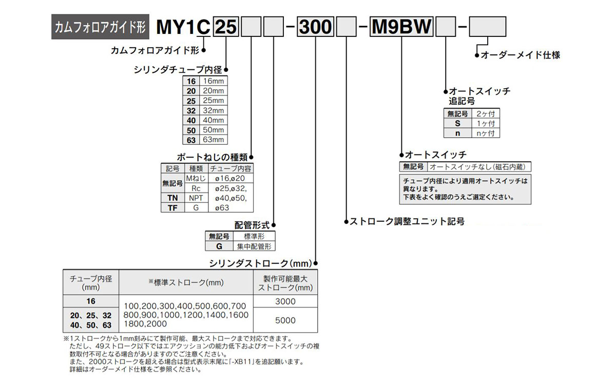
Model number examples
* Please refer to the digital catalog for the stroke adjustment unit.
Optional model display method
Note 1) for details on the adjustment range, refer to the digital catalog.
Note 2) ⌀16 (cylinder inner diameter 16 mm) is available only for A and L units.
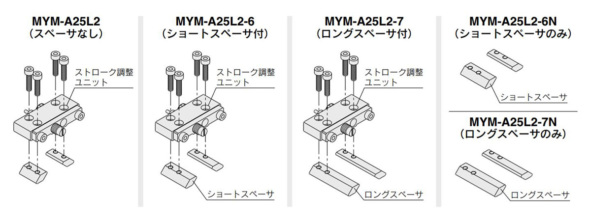
* The spacer is a mounting bracket for fixing the stroke adjustment unit at the intermediate position of the stroke.
Optional components
Side support model
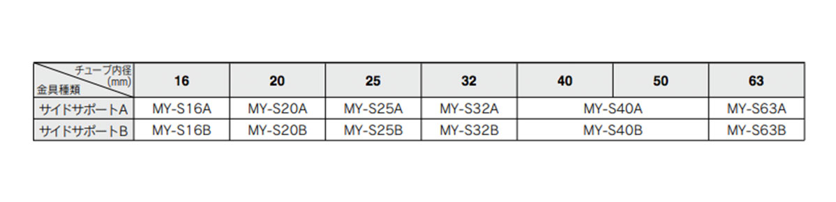
- * Please refer to the digital catalog for details such as dimensions.
- * The side support is a pair on the left and right.
Details of lead wire / connector specifications

Lista numerów części
| Numer części |
|---|
Cena jednostkowa (bez VAT)(Cena jednostkowa z podatkiem) | Standardowa data wysyłki |
|---|
1,032.63 € ( 1,228.83 € ) | 8 dni robocze |
1,142.94 € ( 1,360.10 € ) | 8 dni robocze |
837.74 € ( 996.91 € ) | 8 dni robocze |
807.53 € ( 960.96 € ) | 8 dni robocze |
862.69 € ( 1,026.60 € ) | 8 dni robocze |
1,054.27 € ( 1,254.58 € ) | 8 dni robocze |
1,164.58 € ( 1,385.85 € ) | 8 dni robocze |
798.97 € ( 950.77 € ) | 8 dni robocze |
1,186.21 € ( 1,411.59 € ) | 7 dni robocze |
859.44 € ( 1,022.73 € ) | 8 dni robocze |
926.39 € ( 1,102.40 € ) | 8 dni robocze |
969.74 € ( 1,153.99 € ) | 7 dni robocze |
969.74 € ( 1,153.99 € ) | 8 dni robocze |
1,097.55 € ( 1,306.08 € ) | 8 dni robocze |
1,152.77 € ( 1,371.80 € ) | 8 dni robocze |
969.74 € ( 1,153.99 € ) | 8 dni robocze |
798.97 € ( 950.77 € ) | 8 dni robocze |
969.74 € ( 1,153.99 € ) | 8 dni robocze |
798.97 € ( 950.77 € ) | 8 dni robocze |
1,080.35 € ( 1,285.62 € ) | 8 dni robocze |
1,251.15 € ( 1,488.87 € ) | 8 dni robocze |
859.44 € ( 1,022.73 € ) | 8 dni robocze |
1,102.11 € ( 1,311.51 € ) | 8 dni robocze |
859.44 € ( 1,022.73 € ) | 8 dni robocze |
969.74 € ( 1,153.99 € ) | 7 dni robocze |
798.97 € ( 950.77 € ) | 8 dni robocze |
798.97 € ( 950.77 € ) | 8 dni robocze |
798.97 € ( 950.77 € ) | 8 dni robocze |
1,145.39 € ( 1,363.01 € ) | 8 dni robocze |
798.97 € ( 950.77 € ) | 8 dni robocze |
798.97 € ( 950.77 € ) | 8 dni robocze |
1,188.73 € ( 1,414.59 € ) | 8 dni robocze |
1,359.50 € ( 1,617.81 € ) | 8 dni robocze |
847.52 € ( 1,008.55 € ) | 8 dni robocze |
937.60 € ( 1,115.74 € ) | 8 dni robocze |
969.73 € ( 1,153.98 € ) | 8 dni robocze |
1,034.81 € ( 1,231.42 € ) | 8 dni robocze |
820.53 € ( 976.43 € ) | 8 dni robocze |
991.31 € ( 1,179.66 € ) | 8 dni robocze |
820.53 € ( 976.43 € ) | 8 dni robocze |
991.31 € ( 1,179.66 € ) | 8 dni robocze |
820.53 € ( 976.43 € ) | 8 dni robocze |
820.53 € ( 976.43 € ) | 8 dni robocze |
820.53 € ( 976.43 € ) | 8 dni robocze |
991.31 € ( 1,179.66 € ) | 8 dni robocze |
820.53 € ( 976.43 € ) | 8 dni robocze |
881.00 € ( 1,048.39 € ) | 8 dni robocze |
991.31 € ( 1,179.66 € ) | 8 dni robocze |
902.77 € ( 1,074.30 € ) | 8 dni robocze |
1,085.92 € ( 1,292.24 € ) | 8 dni robocze |
842.31 € ( 1,002.35 € ) | 8 dni robocze |
902.77 € ( 1,074.30 € ) | 8 dni robocze |
1,013.08 € ( 1,205.57 € ) | 8 dni robocze |
1,056.23 € ( 1,256.91 € ) | 8 dni robocze |
842.31 € ( 1,002.35 € ) | 8 dni robocze |
842.31 € ( 1,002.35 € ) | 8 dni robocze |
842.31 € ( 1,002.35 € ) | 8 dni robocze |
842.31 € ( 1,002.35 € ) | 8 dni robocze |
842.29 € ( 1,002.33 € ) | 8 dni robocze |
902.76 € ( 1,074.28 € ) | 8 dni robocze |
Szczegółowe informacje
Podstawowe informacje
An air slide table made by SMC
[Features]
· Capable of smooth operation even when there is an unbalanced load
· Moment-resistant and capable of supporting long strokes
Przestroga
- Product pictures are representations. CAD data is not supported by some of the model numbers.
