CE01 Drip-Proof Cap (for Receptacle / Adapter) (Part Numbers - CAD Download)


- Volume Discount
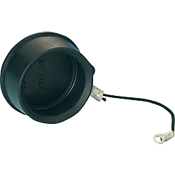
When fitted to a panel jack, in-line adapter or plug, this cap prevents dust and contaminants from entering the mating part when the connector is not connected and prevents accidental contact of the connector with live parts when it is not connected.

● It protects the fitting portion and prevents the intrusion of dust and foreign matter. It also prevents accidents that are caused by the contact with live parts of the connector mating surface while it is not mated.
● It is IP55 when the cap is used.

· It is a dust-proof cap for the panel mount receptacle and relay adapter.
· The dust cap for plug has no string.
Part Number
Once your search is narrowed to one product,
the corresponding part number is displayed here.
Specifications
| Model | Compatible Shell Size | Size (mm) | Weight (g) | |||
| ØA | ØB | ØC | L | |||
| CE1RC-18RA | 18 | 37.5 | 33.1 | 3.2 | 80 | 10.2 |
| CE1RC-20RA | 20 | 42.6 | 38.2 | 3.2 | 100 | 15.6 |
| CE1RC-22RA | 22 | 43.8 | 39.4 | 3.2 | 110 | 12.3 |
| CE1RC-24RA | 24 | 47.0 | 42.6 | 4.3 | 130 | 14.0 |
| CE1RC-28RA | 28 | 53.3 | 49.0 | 4.3 | 150 | 21.3 |
| CE01PC-18RA | 18 | 44.05 | 41.95 | - | - | 20 |
| CE01PC-20RA | 20 | 49.2 | 47.1 | - | - | 24 |
| CE01PC-22RA | 22 | 50.4 | 48.3 | - | - | 25 |
| CE01PC-24RA | 24 | 53.6 | 51.5 | - | - | 27 |
| CE01PC-28RA | 28 | 59.9 | 57.8 | - | - | 32 |
More Information
[ M ]Material / Finish
| Item | Panel Mounting / Relay | For Plug | ||
| Materials | Finish | Materials | Finish | |
| Body | EP Rubber | Black | EP Rubber | Black |
| String | Tetron | Black | — | — |
| Sleeve | Copper Alloy | Tin Plated | — | — |
| Crimp Terminal | Copper Alloy | Tin Plated | — | — |
Part Number
|
|---|
| CE1RC-22RA |
| CE1RC-24RA |
| CE1RC-28RA |
| Part Number |
Standard Unit Price
| Minimum order quantity | Volume Discount | Compatible Shell Size | |
|---|---|---|---|---|---|
18.94 € | 1 | Available | 5 Days | 22 | |
19.40 € | 1 | Available | 5 Days | 24 | |
19.70 € | 1 | Available | 5 Days | 28 |
Loading...
Protection Circuit Connection Structural Diagram

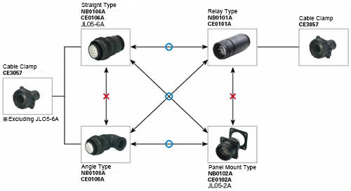
About Compatible Products
NB01 connectors, CE01 connectors, and JL05 connectors are compatible with each other.Combination Method

Material / Finish
| Item | Materials | Finish |
|---|---|---|
| Shell (Body) | Aluminum Alloy | Black Chromate Treatment |
| Insulator | Polyester Resin | UL94V-0, Gray |
| Contact | Copper Alloy | Silver Plating |
| O-ring | Nitrile Rubber | Black |
| Coupling Nut | Aluminum Alloy | Black Chromate Treatment |
| Earth Lug | Steel Alloy | Silver Plating |
| Rear Gasket for Flange | Chloroprene Rubber | Black |
Electrical and Mechanical Properties, Compatible Wires
| Item | Characteristics | |||||||
|---|---|---|---|---|---|---|---|---|
| Rated Current | Contact Size | #20 | #16 | #12 | #8 | |||
| Maximum Value per 1 Piece | 5 A | 13 A | 23 A | 46 A | ||||
| Rated Voltage | Rating Classification | AC (r.m.s) | DC | |||||
| INST | 200 | 250 | ||||||
| A | 500 | 700 | ||||||
| D | 900 | 1,250 | ||||||
| Withstand Voltage | INST | 1,000 VAC (r.m.s) 1 minute | ||||||
| A | 2,000 VAC (r.m.s) 1 minute | |||||||
| D | 2,800 VAC (r.m.s) 1 minute | |||||||
| Insulation Resistance | 5,000 MΩ or more at 500 VDC | |||||||
| Contact Resistance | Contact Size | #20 | #16 | #12 | #8 | |||
| mΩ or less | 8 | 4 | 2 | 0.6 | ||||
| Operating Temperature Range | -55°C ~ +125°C | |||||||
| Waterproofing | IP67 Equivalent | |||||||
| Humidity | Relative Humidity 95% or less | |||||||
| Service Life | 500 Insertions and Removals | |||||||
| NB01 (Solder Type) Compatible Wires (Note 2) |
Contact Size | #16 | #12 | #8 | ||||
| Conductor Cross-sectional Area | 0.75 mm2 or less | 3.5 mm2 or less | 8 mm2 or less | |||||
| AWG Size | 18 or less | 12 or less | 8 or less | |||||
(Note 1) Rated voltage and voltage resistance are shown with rating classification symbols (INST, A; D). Refer as well to the table below.
Contact Arrangement Diagram
| Number of Contacts | 4 | 5 | 7 | 7 | 8 |
|---|---|---|---|---|---|
| Arrangement No. | 22-22 | 18-11 | 20-15 | 24-10 | 22-23 |
| Contact Size | #8 | #12 | #12 | #8 | #12 |
| Contact Arrangement (Note 1) (Note 2) |
 |
 |
 |
 |
 |
| Rating Classification | A | A | A | A | D (4), A (Others) |
| Number of Contacts | 10 | 17 | 19 | 19 | 24 |
|---|---|---|---|---|---|
| Arrangement No. | 18-1 | 20-29 | 18-19A | 22-14 | 24-28 |
| Contact Size | #16 | #16 | #20 | #16 | #16 |
| Contact Arrangement (Note 1) (Note 2) |
 |
 |
 |
 |
 |
| Rating Classification | A (3, 5, 6, 8), INST (Others) |
A | INST | A | INST |
| Number of Contacts | 30 | 37 | 52 | 73 |
| Arrangement No. | 20-30A | 28-21 | 24-52A | 28-73A |
| Contact Size | #20 | #16 | #20 | #20 |
| Contact Arrangement (Note 1) (Note 2) |
 |
 |
 |
 |
| Rating Classification | INST | A | INST | INST |
|---|
(Note 1) View from the male (pin) connector coupling surface.
(Note 2) The ○ in the arrangement table shows the earth terminals (for protection of terminal connections).
Panel Cut Size Drawing

| Compatible Shell Size |
φA ±0.5 |
φB +0.2 -0 |
C ±0.13 |
Mounting Screws (Reference) | Rear Mounting Panel Thickness Limit |
|
|---|---|---|---|---|---|---|
| Inch Screws | Metric Screws | |||||
| 18 | 30.2 | 3.3 | 26.97 | #4-40 | M3 | 3.0 or less |
| 20 | 34.9 | 3.3 | 29.36 | #4-40 | M3 | |
| 22 | 36.6 | 3.3 | 31.75 | #4-40 | M3 | |
| 24 | 39.7 | 4.3 | 34.92 | #6-32 | M4 | |
| 28 | 46.1 | 4.3 | 39.67 | #6-32 | M4 | |
- The specifications and dimensions of some parts may not be fully covered. For exact details, refer to manufacturer catalogs .
Tech Support
- Technical Support
- Tel:+49 69 668173-0 / FAX:+49 69 668173-360
- Technical Inquiry
Metody płatności
Faktura
Przedpłata

Produkcja na zamówienie
Certyfikaty


Copyright © MISUMI Corporation All Rights Reserved.