Tłumaczymy nasz sklep na język polski!
- Number of Teeth(Teeth)
- 15
- 16
- 17
- 18
- 19
- 20
- 21
- 22
- 23
- 24
- 25
- 26
- 27
- 28
- 29
- 30
- 32
- 33
- 34
- 35
- 36
- 38
- 39
- 40
- 42
- 44
- 45
- 46
- 48
- 49
- 50
- 51
- 52
- 54
- 55
- 56
- 57
- 58
- 60
- 62
- 63
- 64
- 65
- 66
- 68
- 69
- 70
- 72
- 75
- 76
- 77
- 78
- 80
- 81
- 84
- 85
- 88
- 90
- 91
- 92
- 95
- 96
- 98
- 99
- 100
- Surface Treatment
- Shaft Bore Config.
- Shaft Bore Dia., Shaft Dia.[8–55/1]
- CAD
- 2D
- 3D
- Szacowane dni wysyłki
- Wszystko
- W ciągu 7 dni robocze


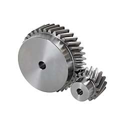
Helical Gears - Module 2.0, Shaft Bore Configurable Type(Lista numerów części: str. 4)
Przestroga
- The tooth shape in the 3D drawing is not generated with CAD data download. Refer to the reference circle on the 3D drawing for more information.
Numer części:
.Rysunek konturowy i tabela specyfikacji
Shape A | Shape B |
[!] Relative positioning of keyway and teeth is not fixed. | ||||||||||||


| Gear dimensions | ||||
| Datum Section of Gears | Teeth perpendicular | |||
| Module | 2.0 | |||
| Pressure Angle | 20° | |||
| Helix Angle | 19° 31′42″ | |||
| Gear Accuracy | JIS B 1702-1, ISO 1328-1, Flank Tolerance Class 8 | |||
| Type | [M] Material | [S] Surface Treatment | [A]Accessory | ||
| Straight Bore | Straight Bore + Tap | Keyway, Keyway + Tap | |||
| HGEARHB | HGEARB | HGEARKB | EN 1.1191 Equiv. | — | Set Screw (EN 1.7220 Equiv. Black Oxide) |
| HGEARHBB | HGEARBB | HGEARKBB | Black Oxide | ||
| HGEARHBG | HGEARBG | HGEARKBG | Electroless Nickel Plating | ||
Specification Table
| Part Number | — | Number of Teeth | — | B | — | Gear Shape | — | P | — | Twisting Direction |
| HGEARHB2.0 | — | 25 | — | 20 | — | A | — | 10 | — | LH |
| HGEARBG2.0 | — | 38 | — | 20 | — | B | — | 20 | — | RH |
| HGEARKB2.0 | — | 18 | — | 20 | — | A | — | 12 | — | LH |
| Part Number | Number of Teeth | B Tooth Width | Gear Shape | Shaft Bore Dia. PH7 (1 mm Increments) | Twisting Direction | d Reference Circle Dia. | D Addendum Circle Dia. | G Dedendum Circle Dia. | H | L | ℓ1 | ℓ2 | M (Coarse) | *1 Allowable Torque (N⋅m) | |||
| Type | Module | Straight Bore Straight Bore + Tap | Keyway Keyway + Tap | Bending Strength | Tooth Surface Strength | ||||||||||||
| Straight Bore (Shape A, Shape B) HGEARHB HGEARHBB HGEARHBG Straight Bore + Tap (Shape B) HGEARB HGEARBB HGEARBG Keyway (Shape A) Keyway + Tap (Shape B) HGEARKB HGEARKBB HGEARKBG | 2.0 | 15 | 20 | A B | 8 to 15 | 8 to 12 | LH (Left) RH (Right) | 31.83 | 35.83 | 26.83 | 22 | 34 | 14 | 7 | M4 | 35.95 | 2.47 |
| 16 | 8 to 16 | 33.95 | 37.95 | 28.95 | 24 | 39.72 | 2.88 | ||||||||||
| 17 | 8 to 19 | 8 to 14 | 36.08 | 40.08 | 31.08 | 27 | 43.56 | 3.32 | |||||||||
| 18 | 8 to 21 | 8 to 16 | 38.20 | 42.20 | 33.20 | 29 | 47.46 | 3.80 | |||||||||
| 19 | 8 to 17 | 40.32 | 44.32 | 35.32 | 31 | 51.41 | 4.54 | ||||||||||
| 20 | 8 to 23 | 8 to 18 | 42.44 | 46.44 | 37.44 | 33 | 55.42 | 5.13 | |||||||||
| 21 | 8 to 19 | 44.56 | 48.56 | 39.56 | 35 | 59.47 | 5.76 | ||||||||||
| 22 | 8 to 25 | 8 to 21 | 46.69 | 50.69 | 41.69 | 37 | 63.57 | 6.43 | |||||||||
| 23 | 8 to 22 | 48.81 | 52.81 | 43.81 | 39 | 67.70 | 7.14 | ||||||||||
| 24 | 8 to 28 | 8 to 23 | 50.93 | 54.93 | 45.93 | 41 | 71.87 | 7.90 | |||||||||
| 25 | 53.05 | 57.05 | 48.05 | 44 | 76.07 | 8.70 | |||||||||||
| 26 | 8 to 30 | 8 to 27 | 55.17 | 59.17 | 50.17 | 46 | 80.30 | 9.54 | |||||||||
| 27 | 8 to 33 | 8 to 30 | 57.30 | 61.30 | 52.30 | 48 | 84.56 | 10.44 | |||||||||
| 28 | 59.42 | 63.42 | 54.42 | 50 | 88.84 | 11.37 | |||||||||||
| 29 | 8 to 35 | 8 to 31 | 61.54 | 65.54 | 56.54 | 52 | 93.15 | 12.36 | |||||||||
| 30 | 8 to 36 | 8 to 32 | 63.66 | 67.66 | 58.66 | 54 | 97.48 | 13.39 | |||||||||
| 32 | 8 to 38 | 8 to 33 | 67.91 | 71.91 | 62.91 | 58 | 106.19 | 15.60 | |||||||||
| 33 | 70.03 | 74.03 | 65.03 | 61 | 110.58 | 16.78 | |||||||||||
| 34 | 10 to 38 | 10 to 33 | 72.15 | 76.15 | 67.15 | 63 | M5 | 114.98 | 18.01 | ||||||||
| 35 | 10 to 40 | 10 to 35 | 74.27 | 78.27 | 69.27 | 65 | 119.39 | 19.28 | |||||||||
| 36 | 10 to 43 | 10 to 37 | 76.39 | 80.39 | 71.39 | 67 | 123.83 | 20.61 | |||||||||
| 38 | 80.64 | 84.64 | 75.64 | 70 | 132.73 | 23.42 | |||||||||||
| 39 | 82.76 | 86.76 | 77.76 | 137.20 | 24.91 | ||||||||||||
| 40 | 10 to 48 | 10 to 40 | 84.88 | 88.88 | 79.88 | 141.68 | 26.44 | ||||||||||
| 42 | 89.13 | 93.13 | 84.13 | 150.67 | 29.67 | ||||||||||||
| 44 | 93.37 | 97.37 | 88.37 | 159.70 | 33.12 | ||||||||||||
| 45 | 95.49 | 99.49 | 90.49 | 164.23 | 34.92 | ||||||||||||
| 46 | 97.62 | 101.62 | 92.62 | 168.76 | 36.78 | ||||||||||||
| 48 | 10 to 50 | 10 to 42 | 101.86 | 105.86 | 96.86 | 177.86 | 40.67 | ||||||||||
| 49 | 103.98 | 107.98 | 98.98 | 182.42 | 42.69 | ||||||||||||
| 50 | 106.10 | 110.10 | 101.10 | 186.98 | 44.78 | ||||||||||||
| 51 | 12 to 52 | 10 to 44 | 108.23 | 112.23 | 103.23 | M6 | 191.55 | 46.92 | |||||||||
| 52 | 110.35 | 114.35 | 105.35 | 196.13 | 49.11 | ||||||||||||
| 54 | 114.59 | 118.59 | 109.59 | 205.30 | 53.68 | ||||||||||||
| 55 | 116.71 | 120.71 | 111.71 | 209.90 | 56.05 | ||||||||||||
| 56 | 118.84 | 122.84 | 113.84 | 214.50 | 58.48 | ||||||||||||
| 57 | 120.96 | 124.96 | 115.96 | 219.10 | 60.97 | ||||||||||||
| 58 | 123.08 | 127.08 | 118.08 | 223.71 | 63.52 | ||||||||||||
| 60 | 127.32 | 131.32 | 122.32 | 232.94 | 68.79 | ||||||||||||
| 62 | 15 to 52 | 15 to 44 | 131.57 | 135.57 | 126.57 | 242.19 | 74.30 | ||||||||||
| 63 | 133.69 | 137.69 | 128.69 | 246.82 | 77.15 | ||||||||||||
| 64 | 135.81 | 139.81 | 130.81 | 251.45 | 80.06 | ||||||||||||
| 65 | 137.93 | 141.93 | 132.93 | 256.08 | 83.03 | ||||||||||||
| 66 | 140.06 | 144.06 | 135.06 | 260.72 | 86.06 | ||||||||||||
| 68 | 144.30 | 148.30 | 139.30 | 270.01 | 92.31 | ||||||||||||
| 69 | 146.42 | 150.42 | 141.42 | 274.66 | 95.53 | ||||||||||||
| Part Number | Number of Teeth | B Tooth Width | Gear Shape | Shaft Bore Dia. PH7 (1 mm Increments) | Twisting Direction | d Reference Circle Dia. | D Addendum Circle Dia. | G Dedendum Circle Dia. | H | L | ℓ1 | ℓ2 | M (Coarse) | *1 Allowable Torque (N⋅m) | |||
| Type | Module | Straight Bore Straight Bore + Tap | Keyway Keyway + Tap | Bending Strength | Tooth Surface Strength | ||||||||||||
| Straight Bore (Shape A, Shape B) HGEARHB HGEARHBB HGEARHBG Straight Bore + Tap (Shape B) HGEARB HGEARBB HGEARBG Keyway (Shape A) Keyway + Tap (Shape B) HGEARKB HGEARKBB HGEARKBG | 2.0 | 70 | 20 | A B | 15 to 52 | 15 to 44 | LH (Left) RH (Right) | 148.54 | 152.54 | 143.54 | 70 | 34 | 14 | 7 | M6 | 279.31 | 98.81 |
| 72 | 152.79 | 156.79 | 147.79 | 288.62 | 105.56 | ||||||||||||
| 75 | 20 to 52 | 20 to 44 | 159.16 | 163.16 | 154.16 | 302.61 | 116.15 | ||||||||||
| 76 | 161.28 | 165.28 | 156.28 | 307.28 | 119.81 | ||||||||||||
| 77 | 163.40 | 167.40 | 158.40 | 311.95 | 123.54 | ||||||||||||
| 78 | 165.52 | 169.52 | 160.52 | 316.62 | 127.33 | ||||||||||||
| 80 | 169.77 | 173.77 | 164.77 | 325.97 | 135.10 | ||||||||||||
| 81 | 20 to 55 | 20 to 47 | 171.89 | 175.89 | 166.89 | 330.65 | 139.08 | ||||||||||
| 84 | 178.25 | 182.25 | 173.25 | 344.69 | 151.42 | ||||||||||||
| 85 | 180.38 | 184.38 | 175.38 | 349.37 | 155.67 | ||||||||||||
| 88 | 186.74 | 190.74 | 181.74 | 363.44 | 168.80 | ||||||||||||
| 90 | 190.99 | 194.99 | 185.99 | 372.82 | 177.89 | ||||||||||||
| 91 | 193.11 | 197.11 | 188.11 | 377.52 | 182.54 | ||||||||||||
| 92 | 195.23 | 199.23 | 190.23 | 382.21 | 187.25 | ||||||||||||
| 95 | 201.60 | 205.60 | 196.60 | 396.31 | 201.79 | ||||||||||||
| 96 | 203.72 | 207.72 | 198.72 | 401.01 | 206.77 | ||||||||||||
| 98 | 207.96 | 211.96 | 202.96 | 410.41 | 216.94 | ||||||||||||
| 99 | 210.08 | 214.08 | 205.08 | 415.12 | 222.12 | ||||||||||||
| 100 | 212.21 | 216.21 | 207.21 | 419.83 | 227.38 | ||||||||||||
[!] The tooth trace is twisted, generating thrust. Design the bearing to be able to withstand axial thrust.
[!] Helical gears engage with the same helix angle with right and left twisting. Please bear this in mind when selecting as part of a set.
*1 Allowable Transmission Forces in the table are reference values calculated with prescribed conditions.
Alterations
| Alterations | Side Through Hole | Side Tapped Hole | Side Counterbored | ||||||||||||||||||||||||||||||||||||||||||||||||||||||||||||||||
| Code | KSC·KFC·KTC | QSC·QFC·QTC | ZFC·ZTC | ||||||||||||||||||||||||||||||||||||||||||||||||||||||||||||||||
| Spec. |
Ordering Code KFC20-K3.5 Applicable Conditions Shape A [ ! ]P+K+4 ≤ KSC (KFC/KTC) ≤ G−K−4  Shape B
·Number of Holes  ·Hole Position  [!] Conditions may vary depending on the shaft bore specs. |
Shape A
 Shape B
 ·Hole Position  [!] Conditions may vary depending on the shaft bore specs. |
 ·Hole Position  [!] Conditions may vary depending on the shaft bore specs. | ||||||||||||||||||||||||||||||||||||||||||||||||||||||||||||||||


Lista numerów części
| Numer części |
|---|
Cena jednostkowa (bez VAT)(Cena jednostkowa z podatkiem) | Standardowa data wysyłki |
|---|
- ( - ) | 7 dni robocze |
- ( - ) | 7 dni robocze |
- ( - ) | 7 dni robocze |
- ( - ) | 7 dni robocze |
- ( - ) | 7 dni robocze |
- ( - ) | 7 dni robocze |
- ( - ) | 7 dni robocze |
- ( - ) | 7 dni robocze |
- ( - ) | 7 dni robocze |
- ( - ) | 7 dni robocze |
- ( - ) | 7 dni robocze |
- ( - ) | 7 dni robocze |
- ( - ) | 7 dni robocze |
- ( - ) | 7 dni robocze |
- ( - ) | 7 dni robocze |
- ( - ) | 7 dni robocze |
- ( - ) | 7 dni robocze |
- ( - ) | 7 dni robocze |
- ( - ) | 7 dni robocze |
- ( - ) | 7 dni robocze |
- ( - ) | 7 dni robocze |
- ( - ) | 7 dni robocze |
- ( - ) | 7 dni robocze |
- ( - ) | 7 dni robocze |
- ( - ) | 7 dni robocze |
- ( - ) | 7 dni robocze |
- ( - ) | 7 dni robocze |
- ( - ) | 7 dni robocze |
- ( - ) | 7 dni robocze |
- ( - ) | 7 dni robocze |
- ( - ) | 7 dni robocze |
- ( - ) | 7 dni robocze |
- ( - ) | 7 dni robocze |
- ( - ) | 7 dni robocze |
- ( - ) | 7 dni robocze |
- ( - ) | 7 dni robocze |
- ( - ) | 7 dni robocze |
- ( - ) | 7 dni robocze |
- ( - ) | 7 dni robocze |
- ( - ) | 7 dni robocze |
- ( - ) | 7 dni robocze |
- ( - ) | 7 dni robocze |
- ( - ) | 7 dni robocze |
- ( - ) | 7 dni robocze |
- ( - ) | 7 dni robocze |
- ( - ) | 7 dni robocze |
- ( - ) | 7 dni robocze |
- ( - ) | 7 dni robocze |
- ( - ) | 7 dni robocze |
- ( - ) | 7 dni robocze |
- ( - ) | 7 dni robocze |
- ( - ) | 7 dni robocze |
- ( - ) | 7 dni robocze |
- ( - ) | 7 dni robocze |
- ( - ) | 7 dni robocze |
- ( - ) | 7 dni robocze |
- ( - ) | 7 dni robocze |
- ( - ) | 7 dni robocze |
- ( - ) | 7 dni robocze |
- ( - ) | 7 dni robocze |
Szczegółowe informacje
Podstawowe informacje
Features: Helical gears have a higher contact ratio than spur gears, resulting in superior transmission accuracy and quieter operation.
Right-twisted helical gears engage with left-twisted helical gears.
Four types of shaft bore are selectable: straight bore, straight bore + tap, keyway, and keyway + tap.
Available alterations: Set screw alteration, tapped hole dimension change, stepped hole, both ends stepped hole, hub cut, hub diameter cut, side slotted hole, side through hole, side tapped hole, and side counterbored hole alterations are possible.
Lineup by moduleModule 1.0Module 1.5Module 2.5Module 3.0
Przestroga
- The tooth shape in the 3D drawing is not generated with CAD data download. Refer to the reference circle on the 3D drawing for more information.
Kontury i specyfikacja
| ·When selecting Keyway types, see the table on the right.  | ■New JIS (B1301) Keyway Dimensions
|
|
| |||||||||||||||||||||||||||||||||||||||||||||||||||||||||||||||||||||||||||||||||||||||||||||||||||||||||||||||||||||||||||||||||||||