Tłumaczymy nasz sklep na język polski!
- Number of Teeth(Teeth)
- 12
- 14
- 15
- 16
- 18
- 20
- 22
- 24
- 25
- 26
- 28
- 30
- 32
- 35
- 36
- 40
- 45
- 48
- 50
- 55
- 56
- 60
- 64
- 70
- 72
- 75
- 80
- 90
- 100
- 120
- Shaft Bore Config.
- Material
- Resin
- MC Nylon
- POM Blue (Polyacetal)
- POM White (Polyacetal)
- Shaft Bore Dia.(Ø)
- 6
- 8
- 10
- 12
- 14
- 15
- 16
- 18
- 20
- 25
- 30
- 35
- 40
[3–56/1Ø jedn.] - Tooth Width B(mm)
- 2
- 3
- 5
- 7
- 8
- 10
- 12
- 15
- 20
- 25
- 30
- 35
- CAD
- 2D
- 3D
- Szacowane dni wysyłki
- Wszystko
- W ciągu 7 dni robocze
- W ciągu 9 dni robocze


Spur Gears / Plastic / Contact Angle 20 Degrees(Lista numerów części: str. 5)

Umieść kursor myszy nad ilustracją, aby ją powiększyć
Numer części:
.Rysunek konturowy i tabela specyfikacji
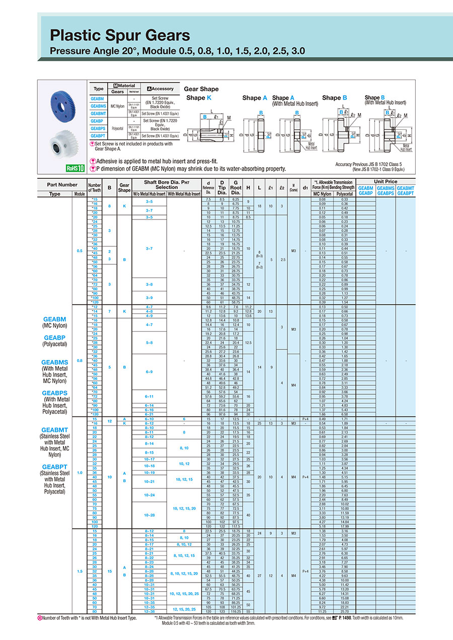
Dimensional Drawing
Shape A Shape A (With Metal Hub Insert) Shape B Shape B (With Metal Hub Insert) Tooth surface accuracy Equivalent to the new JIS B 1702-1 Class 9
(Old JIS B 1702 Class 5)

[ ! ] Adhesive is applied to metal hub insert and press-fit.
[ ! ] P dimension of GEABM (MC Nylon) may shrink due to its water-absorbing property.
| Nominal | PH7 |
| 8 to 10 | +0.015 0 |
| 11 to 18 | +0.018 0 |
| 19 to 30 | +0.021 0 |
| 31 to 50 | +0.025 0 |
| Dimension Range | Tolerance (mm) | |
| Over | or Less | |
| 0.5 | 3 | ±0.1 |
| 3 | 6 | ±0.1 |
| 6 | 30 | ±0.2 |
| 30 | 120 | ±0.3 |
| 120 | 400 | ±0.5 |
Specification Table
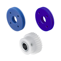
| Products Image No. | Type | [M] Material | [A]Accessory | |
| Gear | Metal Hub Insert | |||
(1) | GEABM | MC Nylon | — | Set Screw (EN 1.7220 Equiv., Black Oxide) |
| GEABMS | EN 1.1191 Equiv. | |||
| GEABMT | EN 1.4301 Equiv. | Set Screw (EN 1.4301 Equiv.) | ||
(2) | GEABP | White Polyacetal | — | Set Screw (EN 1.7220 Equiv., Black Oxide) |
| GEABPS | EN 1.1191 Equiv. | |||
| GEABPT | EN 1.4301 Equiv. | Set Screw (EN 1.4301 Equiv.) | ||
(3) | GEABA | Blue Polyacetal | - | Set Screw (EN 1.7220 Equiv., Black Oxide) |
| GEABAS | EN 1.1191 Equiv. | |||
| GEABAT | EN 1.4301 Equiv. | Set Screw (EN 1.4301 Equiv.) | ||
Specification Table
| Part Number | — | Number of Teeth | — | B | — | Gear Shape | — | P |
| GEABM1.0 GEABPS2.0 GEABM0.5 | — — — | 20 40 20 | — — — | 10 20 8 | — — — | A B K | — — — | 8 20 7 |
| Part Number | Number of Teeth | B | Gear Shape | Shaft Bore Dia. PH7 Unit: mm | d Reference Circle Dia. | D Addendum Circle Dia. | G Dedendum Circle Dia. | H | L | ℓ1 | ℓ2 | M (Coarse) | d1 | * 1 Allowable Transmission Force (N⋅m) Bending Strength | |||
| Type | Module | W/o Metal Hub Insert | With Metal Hub Insert | MC Nylon | Polyacetal | ||||||||||||
| GEABM (MC Nylon) GEABP (White Polyacetal) GEABA (Blue Polyacetal) | 0.5 | 15 | 8 | K | 3 to 5 | — | 7.5 | 8.5 | 6.25 | 9 | 18 | 10 | 3 | M3 | — | 0.08 | 0.33 |
| 16 | 8 | 9 | 6.75 | 0.09 | 0.36 | ||||||||||||
| 18 | 3 to 7 | 9 | 10 | 7.75 | 10 | 0.11 | 0.42 | ||||||||||
| 20 | 10 | 11 | 8.75 | 11 | 0.12 | 0.49 | |||||||||||
| 20 | 3 5 | B | 3 to 5 | 10 | 11 | 8.75 | 8.5 | 10 (B = 5) 8 (B = 3) 7 (B = 2) | 5 | 2.5 | 0.05 | 0.18 | |||||
| 24 | 3 to 7 | 12 | 13 | 10.75 | 10 | 0.06 | 0.23 | ||||||||||
| 25 | 12.5 | 13.5 | 11.25 | 0.06 | 0.24 | ||||||||||||
| 28 | 14 | 15 | 12.75 | 0.07 | 0.28 | ||||||||||||
| 30 | 15 | 16 | 13.75 | 0.08 | 0.31 | ||||||||||||
| 32 | 16 | 17 | 14.75 | 0.08 | 0.33 | ||||||||||||
| 36 | 18 | 19 | 16.75 | 0.10 | 0.39 | ||||||||||||
| 40 | 2 3 5 | 20 | 21 | 18.75 | 0.11 | 0.44 | |||||||||||
| 45 | 22.5 | 23.5 | 21.25 | 0.13 | 0.51 | ||||||||||||
| 48 | 24 | 25 | 22.75 | 0.14 | 0.55 | ||||||||||||
| 50 | 25 | 26 | 23.75 | 0.15 | 0.58 | ||||||||||||
| 56 | 3 5 | 28 | 29 | 26.75 | 0.17 | 0.67 | |||||||||||
| 60 | 30 | 31 | 28.75 | 0.18 | 0.73 | ||||||||||||
| 64 | 32 | 33 | 30.75 | 0.20 | 0.78 | ||||||||||||
| 70 | 3 to 8 | 35 | 36 | 33.75 | 12 | 0.22 | 0.86 | ||||||||||
| 72 | 36 | 37 | 34.75 | 0.22 | 0.89 | ||||||||||||
| 80 | 40 | 41 | 38.75 | 0.25 | 0.99 | ||||||||||||
| 90 | 3 to 9 | 45 | 46 | 43.75 | 14 | 0.28 | 1.13 | ||||||||||
| 100 | 50 | 51 | 48.75 | 0.32 | 1.27 | ||||||||||||
| 120 | 60 | 61 | 58.75 | 0.39 | 1.54 | ||||||||||||
| 0.8 | 12 | 7 | K | 4 to 6 | — | 9.6 | 11.2 | 7.6 | 11.2 | 20 | 13 | 3 | M3 | — | 0.13 | 0.50 | |
| 14 | 4 to 8 | 11.2 | 12.8 | 9.2 | 12.8 | 0.17 | 0.66 | ||||||||||
| 15 | 4 to 9 | 12 | 13.6 | 10 | 13.6 | 0.18 | 0.73 | ||||||||||
| 16 | 5 8 | B | 4 to 7 | 12.8 | 14.4 | 10.8 | 10 | 17 (B = 8) 14 (B = 5) | 9 | 0.15 | 0.58 | ||||||
| 18 | 14.4 | 16 | 12.4 | 0.17 | 0.67 | ||||||||||||
| 20 | 16 | 17.6 | 14 | 0.20 | 0.78 | ||||||||||||
| 24 | 5 to 8 | 19.2 | 20.8 | 17.2 | 12.5 | 0.25 | 0.98 | ||||||||||
| 25 | 20 | 21.6 | 18 | 0.26 | 1.04 | ||||||||||||
| 28 | 22.4 | 24 | 20.4 | 0.30 | 1.20 | ||||||||||||
| 30 | 24 | 25.6 | 22 | 0.33 | 1.30 | ||||||||||||
| 32 | 25.6 | 27.2 | 23.6 | 4 | 0.36 | 1.42 | |||||||||||
| 36 | 6 to 9 | 28.8 | 30.4 | 26.8 | 14 | M4 | 0.42 | 1.65 | |||||||||
| 40 | 32 | 33.6 | 30 | 0.47 | 1.88 | ||||||||||||
| 45 | 36 | 37.6 | 34 | 0.55 | 2.18 | ||||||||||||
| 48 | 38.4 | 40 | 36.4 | 0.59 | 2.36 | ||||||||||||
| 50 | 40 | 41.6 | 38 | 0.63 | 2.49 | ||||||||||||
| 56 | 44.8 | 46.4 | 42.8 | 0.72 | 2.85 | ||||||||||||
| 60 | 48 | 49.6 | 46 | 0.78 | 3.11 | ||||||||||||
| 64 | 51.2 | 52.8 | 49.2 | 0.84 | 3.33 | ||||||||||||
| 70 | 6 to 11 | 56 | 57.6 | 54 | 16 | 0.92 | 3.66 | ||||||||||
| 72 | 57.6 | 59.2 | 55.6 | 0.95 | 3.78 | ||||||||||||
| 80 | 64 | 65.6 | 62 | 1.07 | 4.24 | ||||||||||||
| 90 | 6 to 14 | 72 | 73.6 | 70 | 20 | 1.21 | 4.83 | ||||||||||
| 100 | 6 to 16 | 80 | 81.6 | 78 | 24 | 1.37 | 5.43 | ||||||||||
| 120 | 6 to 21 | 96 | 97.6 | 94 | 30 | 1.66 | 6.58 | ||||||||||
" ! " To select the maximum face width (B) within each module, Gear Shape A: B ≤ P × 5, Shape B: Select within the range of L ≤ P × 5.
*1 Allowable Transmission Forces in the table are reference values calculated with prescribed conditions.
Module 0.5 with 20 to 120 teeth is calculated as tooth width 3 mm.
Module 0.8 with 16 to 120 teeth is calculated as tooth width 5 mm.
| Part Number | Number of Teeth | B | Gear Shape | Shaft Bore Dia. PH7 Unit: mm | d Reference Circle Dia. | D Addendum Circle Dia. | G Dedendum Circle Dia. | H | L | ℓ1 | ℓ2 | M (Coarse) | d1 | * 1 Allowable Transmission Force (N⋅m) Bending Strength | |||
| Type | Module | W/o Metal Hub Insert | With Metal Hub Insert | MC Nylon | Polyacetal | ||||||||||||
| GEABM (MC Nylon) GEABP (White Polyacetal) GEABA (Blue Polyacetal) GEABMS (With Metal Hub Insert / MC Nylon) GEABPS (With Metal Hub Insert / White Polyacetal) GEABAS (With Metal Hub Insert / Blue Polyacetal) GEABMT (With SUS Metal Hub Insert MC Nylon) GEABPT (With SUS Metal Hub Insert White Polyacetal) GEABAT (With SUS Metal Hub Insert Blue Polyacetal) | 1.0 | 15 | 12 | A | 6 to 10 | 6 | 15 | 17 | 12.5 | — | — | — | — | — | P+4 | 0.49 | 1.71 |
| * 16 | K | 8 to 12 | — | 16 | 18 | 13.5 | 18 | 25 | 13 | 3 | M3 | — | 0.54 | 1.89 | |||
| 18 | 8 10 15 | A B | 8 to 10 | 8 | 18 | 20 | 15.5 | 15 | 25 (B = 15) 20 (B = 10) 18 (B = 8) | 10 | 4 | M4 | P+4 | 0.42 | 1.47 | ||
| 20 | 8 to 11 | 20 | 22 | 17.5 | 16 | 0.49 | 1.70 | ||||||||||
| 22 | 8 to 12 | 22 | 24 | 19.5 | 18 | 0.55 | 1.93 | ||||||||||
| 24 | 8 to 14 | 8·10 | 24 | 26 | 21.5 | 20 | 0.62 | 2.15 | |||||||||
| 25 | 25 | 27 | 22.5 | 0.66 | 2.27 | ||||||||||||
| 26 | 8 to 15 | 26 | 28 | 23.5 | 22 | 0.69 | 2.40 | ||||||||||
| 28 | 28 | 30 | 25.5 | 0.75 | 2.62 | ||||||||||||
| 30 | 10 to 17 | 10·12 | 30 | 32 | 27.5 | 25 | 0.82 | 2.85 | |||||||||
| 32 | 10 to 18 | 32 | 34 | 29.5 | 26 | 0.89 | 3.10 | ||||||||||
| 35 | 35 | 37 | 32.5 | 1.00 | 3.47 | ||||||||||||
| 36 | 10 to 19 | 10·12·15 | 36 | 38 | 33.5 | 28 | 1.04 | 3.61 | |||||||||
| 40 | 10 to 21 | 40 | 42 | 37.5 | 30 | 1.18 | 4.12 | ||||||||||
| 45 | 45 | 47 | 42.5 | 1.37 | 4.76 | ||||||||||||
| 48 | 48 | 50 | 45.5 | 1.49 | 5.16 | ||||||||||||
| 50 | 10 to 24 | 10·12·15·20 | 50 | 52 | 47.5 | 35 | 1.57 | 5.44 | |||||||||
| 55 | 55 | 57 | 52.5 | 1.76 | 6.10 | ||||||||||||
| 60 | 60 | 62 | 57.5 | 1.95 | 6.79 | ||||||||||||
| 70 | 10 to 28 | 70 | 72 | 67.5 | 40 | 2.30 | 8.02 | ||||||||||
| 75 | 75 | 77 | 72.5 | 2.49 | 8.64 | ||||||||||||
| 80 | 80 | 82 | 77.5 | 2.66 | 9.27 | ||||||||||||
| 90 | 90 | 92 | 87.5 | 3.04 | 10.55 | ||||||||||||
| 100 | 100 | 102 | 97.5 | 3.42 | 11.87 | ||||||||||||
| 120 | 120 | 122 | 117.5 | 4.14 | 14.39 | ||||||||||||
| 1.5 | 15 | 10 15 20 | A B | 8 to 12 | 8 | 22.5 | 25.5 | 18.75 | 18 | 29 (B=20) 24 (B=15) 19 (B = 10) | 9 | 3 | M3 | P+4 | 0.92 | 2.11 | |
| 16 | 8 to 14 | 8·10 | 24 | 27 | 20.25 | 20 | 1.02 | 2.33 | |||||||||
| 18 | 8 to 15 | 27 | 30 | 23.25 | 22 | 32 (B = 20) 27 (B = 15) 22 (B = 10) | 12 | 4 | M4 | 1.19 | 2.72 | ||||||
| 20 | 8 to 17 | 8·10·12 | 30 | 33 | 26.25 | 25 | 1.38 | 3.15 | |||||||||
| 24 | 8 to 21 | 8·10·12·15 | 36 | 39 | 32.25 | 30 | 1.74 | 3.98 | |||||||||
| 25 | 8 to 21 | 37.5 | 40.5 | 33.75 | 1.84 | 4.20 | |||||||||||
| 26 | 8 to 22 | 39 | 42 | 35.25 | 32 | 1.94 | 4.43 | ||||||||||
| 28 | 8 to 23 | 42 | 45 | 38.25 | 34 | 2.12 | 4.85 | ||||||||||
| 30 | 8 to 24 | 8·10·12·15·20 | 45 | 48 | 41.25 | 35 | 2.31 | 5.27 | |||||||||
| 32 | 8 to 28 | 48 | 51 | 44.25 | 40 | 2.51 | 5.72 | ||||||||||
| 35 | 8 to 28 | 52.5 | 55.5 | 48.75 | 2.81 | 6.42 | |||||||||||
| 36 | 8 to 28 | 54 | 57 | 50.25 | 2.92 | 6.67 | |||||||||||
| 40 | 10 to 31 | 10·12·15·20·25 | 60 | 63 | 56.25 | 45 | 3.33 | 7.61 | |||||||||
| 45 | 10 to 31 | 67.5 | 70.5 | 63.75 | 3.85 | 8.80 | |||||||||||
| 48 | 10 to 31 | 72 | 75 | 68.25 | 4.18 | 9.54 | |||||||||||
| 50 | 10 to 31 | 75 | 78 | 71.25 | 4.40 | 10.05 | |||||||||||
| 60 | 10 to 35 | 90 | 93 | 86.25 | 50 | 5.49 | 12.55 | ||||||||||
| 70 | 12 to 35 | 12·15·20·25 | 105 | 108 | 101.25 | 6.48 | 14.81 | ||||||||||
| 80 | 12 to 38 | 120 | 123 | 116.25 | 55 | 7.50 | 17.13 | ||||||||||
| 2.0 | * 12 | 15 20 25 | A B | 10 to 12 | — | 24 | 28 | 19.0 | 18 | 39 (B = 25) 34 (B = 20) 29 (B = 15) | 14 | 4 | M4 | — | 1.69 | 1.84 | |
| 14 | 10 to 14 | 10 | 28 | 32 | 23.0 | 20 | P+4 | 2.22 | 2.42 | ||||||||
| 15 | 10 to 16 | 10·12 | 30 | 34 | 25.0 | 24 | 2.46 | 2.69 | |||||||||
| 16 | 10 to 17 | 10·12·15 | 32 | 36 | 27.0 | 25 | 2.72 | 2.98 | |||||||||
| 18 | 10 to 21 | 36 | 40 | 31.0 | 30 | 3.18 | 3.47 | ||||||||||
| 20 | 10 to 23 | 40 | 44 | 35.0 | 33 | 3.68 | 4.02 | ||||||||||
| 24 | 10 to 28 | 10·12·15·20 | 48 | 52 | 43.0 | 40 | 4.64 | 5.08 | |||||||||
| 25 | 50 | 54 | 45.0 | 4.91 | 5.36 | ||||||||||||
| 28 | 10 to 31 | 10·12·15·20·25 | 56 | 60 | 51.0 | 45 | 5.66 | 6.18 | |||||||||
| 30 | 10 to 33 | 60 | 64 | 55.0 | 48 | 6.15 | 6.72 | ||||||||||
| 32 | 12 to 35 | 12·15·20·25·30 | 64 | 68 | 59.0 | 50 | 6.68 | 7.30 | |||||||||
| 35 | 12 to 35 | 70 | 74 | 65.0 | 7.49 | 8.19 | |||||||||||
| 36 | 12 to 35 | 72 | 76 | 67.0 | 7.79 | 8.51 | |||||||||||
| 40 | 12 to 42 | 80 | 84 | 75.0 | 60 | 8.90 | 9.71 | ||||||||||
| 45 | 90 | 94 | 85.0 | 10.28 | 11.23 | ||||||||||||
| 48 | 96 | 100 | 91.0 | 11.14 | 12.17 | ||||||||||||
| 50 | 100 | 104 | 95.0 | 11.74 | 12.83 | ||||||||||||
| 60 | 120 | 124 | 115.0 | 14.66 | 16.01 | ||||||||||||
" ! " To select the maximum face width (B) within each module, Gear Shape A: B ≤ P × 5, Shape B: Select within the range of L ≤ P × 5
[NG] Number of Teeth with * is not With Metal Hub Insert Type.
*1 Allowable Transmission Forces in the table are reference values calculated with prescribed conditions.
Calculated with the thinnest tooth width for each module 1.0, 1.5, and 2.0.
Please calculate based on the tooth width to be selected.
(Example) [Selection Conditions] Module 1.0, face width 40, MC nylon, face width B = 15
Bending Strength: 1.18 × 15÷8=2.21 N⋅m
| Part Number | Number of Teeth | B | Gear Shape | Shaft Bore Dia. PH7 Unit: mm | d Reference Circle Dia. | D Addendum Circle Dia. | G Dedendum Circle Dia. | H | L | ℓ1 | ℓ2 | M (Coarse) | d1 | * 1 Allowable Transmission Force (N⋅m) Bending Strength | |||
| Type | Module | W/o Metal Hub Insert | With Metal Hub Insert | MC Nylon | Polyacetal | ||||||||||||
| GEABM (MC Nylon) GEABMS (With Metal Hub Insert / MC Nylon) GEABMT (With SUS Metal Hub Insert MC Nylon) | 2.5 | 12 | 20 25 30 | A B | 10 to 16 | 10 | 30 | 35 | 23.75 | 23 | 42 (B = 30) 37 (B = 25) 32 (B=20) | 12 | 6 | M5 | P+6 | 3.51 | — |
| 14 | 10 to 17 | 10 | 35 | 40 | 28.75 | 25 | 4.62 | ||||||||||
| 15 | 12 to 21 | 10·12·15 | 37.5 | 42.5 | 31.25 | 30 | 5.13 | ||||||||||
| 16 | 12 to 22 | 40 | 45 | 33.75 | 32 | 5.67 | |||||||||||
| 18 | 12 to 26 | 10·12·15·20 | 45 | 50 | 38.75 | 38 | 6.62 | ||||||||||
| 20 | 12 to 28 | 50 | 55 | 43.75 | 40 | 7.67 | |||||||||||
| 22 | 12 to 30 | 12·15·20 | 55 | 60 | 48.75 | 44 | M6 | P+8 | 8.67 | ||||||||
| 24 | 12 to 33 | 12·15·20·25 | 60 | 65 | 53.75 | 48 | 9.68 | ||||||||||
| 25 | 12 to 35 | 62.5 | 67.5 | 56.25 | 50 | 10.22 | |||||||||||
| 28 | 12 to 42 | 12·15·20·25·30 | 70 | 75 | 63.75 | 60 | 11.78 | ||||||||||
| 30 | 12 to 45 | 75 | 80 | 68.75 | 65 | 12.82 | |||||||||||
| 32 | 15 to 49 | 15·20·25·30·35 | 80 | 85 | 73.75 | 70 | 13.92 | ||||||||||
| 35 | 87.5 | 92.5 | 81.25 | 15.62 | |||||||||||||
| 36 | 90 | 95 | 83.75 | 16.22 | |||||||||||||
| 40 | 100 | 105 | 93.75 | 18.52 | |||||||||||||
| 45 | 112.5 | 117.5 | 106.25 | 21.41 | |||||||||||||
| 48 | 120 | 125 | 113.75 | 23.21 | |||||||||||||
| 50 | 125 | 130 | 118.75 | 24.46 | |||||||||||||
| 3.0 | 12 | 25 30 35 | A B | 12 to 19 | 12 | 36 | 42 | 28.5 | 28 | 50 (B = 35) 45 (B = 30) 40 (B=25) | 15 | 7.5 | M5 | P+6 | 6.32 | — | |
| 14 | 12 to 22 | 12·15 | 42 | 48 | 34.5 | 32 | 8.32 | ||||||||||
| 15 | 14 to 25 | 45 | 51 | 37.5 | 36 | 9.23 | |||||||||||
| 16 | 14 to 26 | 12·15·20 | 48 | 54 | 40.5 | 38 | 10.21 | ||||||||||
| 18 | 14 to 28 | 54 | 60 | 46.5 | 40 | 11.93 | |||||||||||
| 20 | 14 to 35 | 15·20·25 | 60 | 66 | 52.5 | 50 | M6 | P+8 | 13.80 | ||||||||
| 22 | 14 to 37 | 66 | 72 | 58.5 | 54 | 15.60 | |||||||||||
| 24 | 14 to 40 | 15·20·25·30 | 72 | 78 | 64.5 | 58 | 17.42 | ||||||||||
| 25 | 14 to 42 | 75 | 81 | 67.5 | 60 | 18.40 | |||||||||||
| 28 | 14 to 49 | 15·20·25·30·35 | 84 | 90 | 76.5 | 70 | 21.21 | ||||||||||
| 30 | 14 to 52 | 90 | 96 | 82.5 | 75 | 23.07 | |||||||||||
| 32 | 18 to 52 | 20·25·30·35·40 | 96 | 102 | 88.5 | 25.05 | |||||||||||
| 35 | 18 to 56 | 105 | 111 | 97.5 | 80 | 28.11 | |||||||||||
| 36 | 108 | 114 | 100.5 | 29.18 | |||||||||||||
| 40 | 120 | 126 | 112.5 | 33.34 | |||||||||||||
| 45 | 135 | 141 | 127.5 | 38.54 | |||||||||||||
" ! " To select the maximum face width (B) within each module, Gear Shape A: B ≤ P × 5, Shape B: Select within the range of L ≤ P × 5.
*1 Allowable Transmission Forces in the table are reference values calculated with prescribed conditions.
Calculated with the thinnest tooth width for modules 2.5 and 3.0.
Please calculate based on the tooth width to be selected.
(Example) [Selection Conditions] Module 3.0, face width 40, MC nylon, face width B = 35
Bending Strength: 33.34 × 35÷25=46.67 N⋅m
Alterations
| Alterations | Set Screw Alteration | Tapped Hole Dimension Change | Root matching | |||||||||||
| Code | KC90·KC120 | TPC | GBA | |||||||||||
| Spec. | KC90: Adds another set screw at 90° position. KC120: Adds another set screw at 120° position. A set screw is added. Ordering Code KC90 Applicable Conditions [NG] Not applicable to Shape A [NG] Not applicable to Straight Bore Type KC90 KC120 | Changes the tapped hole dimension. Ordering Code TPC4 Applicable conditions [NG] Not applicable to Shape A Standard Conditions [ ! ] ℓ1 - ℓ2 > TPC/2 |
| Align the bottom of the gear with the phase of the tap. Phase Adjustment Tolerance ±0.3 (Reference Value) Ordering Code GBA Applicable Conditions [ ! ] Applicable to 19 teeth or more [ ! ] Applicable to Module 1.0, 1.5, 2.0, 2.5, and 3.0 only | ||||||||||
 |  | |||||||||||||
| Alterations | Stepped Hole | Both Ends Stepped Hole | Hub Cut | ||||||||||||||||
| Code | DHL·DHR | WDH | BS | ||||||||||||||||
| Spec. | Changes shaft bores to stepped bores. Dimension Increments Z: 1 mm Increments J: 0.1 mm Increments Ordering Code DHL-Z20-4.0 Applicable Conditions [NG] Not applicable to With Metal Hub Insert Type [NG ] Not applicable to Shape K [ ! ] No tapped holes for Shape B. Standard conditions
| Changes shaft bores to both ends stepped hole. Dimension Increments Q, R, S, T: 1 mm Increments S, T ≥ 3 Ordering Code WDH-Q10-R10-S3-T3 Applicable Conditions [NG] Not applicable to With Metal Hub Insert Type [NG ] Not applicable to Shape K [ ! ] No tapped holes for Shape B. Standard conditions
| Cuts the hub length to the specified length. Increments 0.5 mm Ordering Code BS6.5 Applicable Conditions [NG] Not applicable to Shape A, K Standard conditions [!] Straight Bore: 0 ≤ BS ≤ ℓ1 [!] Straight Bore + Tapped Type: BS=0; M+3 ≤ BS ≤ ℓ1 " ! " Keyway + Tapped Type: BS=0; M+3 ≤ BS ≤ ℓ1 [ ! ] If BS = 0, no tapped hole  |


| M | C |
| M3 | 3.5 |
| M4 | 4.5 |
| M5 | 5.5 |
| M6 | 6.5 |
| Alterations | Side Slotted Hole | Side Through Hole | |
| Code | LFC·LTC | KFC·KTC | |
| Spec. | Machines slotted holes on the side surface (30°). Dimension Increments LFC, LTC: 1 mm Increments Select M M3, M4, M5, M6 Ordering Code LFC20-M3 | Machines through holes on the side surface. Increments KFC, KTC: 1 mm Increments K: 0.5 mm Increments Select M K3.0 to K6.0 Applicable Conditions [NG] Not applicable to Shape K | |
| Applicable Conditions [ ! ] Applicable to Shape A only Standard Conditions [ ! ] Without Metal Hub Insert: P + C + 4 ≤ LFC (LTC) ≤ G - C - 4 [ ! ] With Metal Hub Insert: d1 + C + 4 ≤ LFC(LTC) ≤ G - C - 4 | Shape A Ordering Code KFC20-K3.5 Standard Conditions [ ! ] Without Metal Hub Insert: P + K + 4 ≤ KFC (KTC) ≤ G - K - 4 [ ! ] With Metal Hub Insert: d1 + K + 4 ≤ KFC(LTC) ≤ G - K - 4 | Shape B Ordering Code KFC20-K3.5 Standard Conditions [ ! ] Without Metal Hub Insert: P + K + 4 ≤ KFC (KTC) ≤ H - K - 4; H + K + 4 ≤ KFC (KTC) ≤ G - K - 4 [ ! ] With Metal Hub Insert: d1 + K + 4 ≤ KFC (KTC) ≤ H - K - 4; H + K + 4 ≤ KFC (KTC) ≤ G - K - 4 | |
 |  |  | |
Lista numerów części
| Numer części |
|---|
Cena jednostkowa (bez VAT)(Cena jednostkowa z podatkiem) | Standardowa data wysyłki |
|---|
- ( - ) | 7 dni robocze |
- ( - ) | 7 dni robocze |
- ( - ) | 7 dni robocze |
- ( - ) | 7 dni robocze |
- ( - ) | 7 dni robocze |
- ( - ) | 7 dni robocze |
- ( - ) | 7 dni robocze |
- ( - ) | 7 dni robocze |
- ( - ) | 7 dni robocze |
- ( - ) | 7 dni robocze |
- ( - ) | 7 dni robocze |
- ( - ) | 7 dni robocze |
- ( - ) | 7 dni robocze |
- ( - ) | 7 dni robocze |
- ( - ) | 7 dni robocze |
- ( - ) | 7 dni robocze |
- ( - ) | 7 dni robocze |
- ( - ) | 7 dni robocze |
- ( - ) | 7 dni robocze |
- ( - ) | 7 dni robocze |
- ( - ) | 7 dni robocze |
- ( - ) | 7 dni robocze |
- ( - ) | 7 dni robocze |
- ( - ) | 7 dni robocze |
- ( - ) | 7 dni robocze |
- ( - ) | 7 dni robocze |
- ( - ) | 7 dni robocze |
- ( - ) | 7 dni robocze |
- ( - ) | 7 dni robocze |
- ( - ) | 7 dni robocze |
- ( - ) | 7 dni robocze |
- ( - ) | 7 dni robocze |
- ( - ) | 7 dni robocze |
- ( - ) | 7 dni robocze |
- ( - ) | 7 dni robocze |
- ( - ) | 7 dni robocze |
- ( - ) | 7 dni robocze |
- ( - ) | 7 dni robocze |
- ( - ) | 7 dni robocze |
- ( - ) | 7 dni robocze |
- ( - ) | 7 dni robocze |
- ( - ) | 7 dni robocze |
- ( - ) | 7 dni robocze |
- ( - ) | 7 dni robocze |
- ( - ) | 7 dni robocze |
- ( - ) | 7 dni robocze |
- ( - ) | 7 dni robocze |
- ( - ) | 7 dni robocze |
- ( - ) | 7 dni robocze |
- ( - ) | 7 dni robocze |
- ( - ) | 7 dni robocze |
- ( - ) | 7 dni robocze |
- ( - ) | 7 dni robocze |
- ( - ) | 7 dni robocze |
- ( - ) | 7 dni robocze |
- ( - ) | 7 dni robocze |
- ( - ) | 7 dni robocze |
- ( - ) | 7 dni robocze |
- ( - ) | 7 dni robocze |
- ( - ) | 7 dni robocze |
Szczegółowe informacje
Kontury i specyfikacja
General Information - Spur Gears
Selection details of spur gears
- Material: steel, stainless steel, sintered steel, nylon, polyacetal, brass, aluminum, cast iron
- Coatings: burnished, nickel-plated
- Heat treatment: induction hardened
- Shaft diameter tolerances: H7, H8
- Tooth flank clearance: N5, N7, N8, N9, N12
- Module: 0.3, 0.5, 0.75, 0.8, 1, 1.25, 1.5, 2, 2.5, 3, 4, 4.5, 5, 6, 8, 10, 15, 20
- Pressure angle: 20°
- Shaft diameter: 2 mm to 50 mm
- Number of teeth: 8 to 200
- Tooth width: 2 mm to 90 mm
Description/Basics
The spur gears offered are generally machine elements that serve the non-slip transmission of force, movement transmission or movement change. The teeth of the cylinder wheels grip each other during transmission and largely roll over the tooth flanks. The tooth shape of the spur gear is convexly shaped in the shaped tooth system. At the beginning of the intervention, a rolling resistance acts on the tooth flank, which becomes a sliding friction in the course of the rotation.
A combination of gear wheels and rack gears is useful in the construction of rack gear. This allows motor rotary motion or other rotary motion to be converted into linear motion. rack gear boxes are theoretically possible in an endless assembly. Limits here only set the length of the rack gears for the rack gear drive.
Gear wheels with straight gearing are particularly suitable for the construction of gearboxes. The advantage of straight gearing as opposed to helical gears, is the possibility of transmitting a higher torque. It should be noted that with increasing speed within the transmission ratio or reduction, the torque to be transmitted decreases.
When designing spur gear pairs, the ratio of the gear ratio (number of teeth) and the module of the respective gear wheels must be observed.
The backlash is another important factor that must be considered during construction. Reverse play is understood as the result of the play that the change in the direction of rotation of a single gear wheel pair between the teeth. The risk of reverse play can be reduced if either the diameter or the number of teeth of the cogwheel pairing do not deviate too much from one another. If high wear is to be expected due to the pairing of gears, the MISUMI online shop offers gears with a hardened key-type.
For applications with the same rotational direction, it is possible to use an intermediate gear with integrated bearing on a cantilever shaft. The bearing number used can be found under the tab More Information. An overview of tolerances and permissible radial bearing deviations can be found in the following PDF.
In addition to gear wheels, MISUMI also offers suitable rotary shafts for the construction of a transmission. The straight front wheels can be assembled on these and secured with a set screw or machine keys (key with adjusting screw). This PDF provides an overview of the configurable mountings for the shaft rotation and keyway tolerances.
The continuous adjusting of a spur gear can be realized, among other things, by means of a clamping sleeve. The MISUMI online shop offers spur gears with clamping sleeve. Alternatively, we also offer individual keyless bushing that you can customize to your needs.
Application Examples - Spur Gears
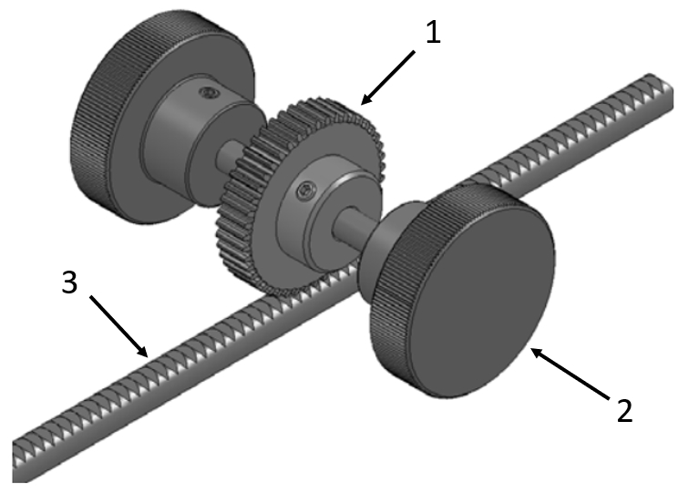
Application example - spur gear with rack gear
(1) Spur gear, (2) Clamping knobs, (3) Rack gear

Application example - spur gear
(1) Spur gear, (2) Workpiece, (3) Rollers
Industrial Applications