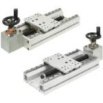
Manually Operated Units / Handwheel Direction Configurable (Part Numbers - CAD Download)

Part Number
Once your search is narrowed to one product,
the corresponding part number is displayed here.
- Drawing / Specifications
- 3D Preview 3D preview is available after complete configuration
- Part Numbers
- More Information
- Catalog
KUEF
*1) Stroke limit is where stroke reaches the mechanical limit.
[ ! ] Use M6 nuts.
Handwheel Type C 

| Handwheel Type A | Handwheel Type B | |
 |  |
[ ! ] Use M6 nuts.
■ Components
| Parts | Base | Table | Trapezoidal Thread | Lead Screw Nut |
| Material | Aluminum Alloy | Aluminum Alloy | EN 1.1191 Equiv. | Brass |
| Surface Treatment | Clear Anodize | Clear Anodize | Black Oxide | — |
| Parts | Nut Bracket | Side Plate | Bevel Gear | Cover |
| Material | Aluminum Alloy | Aluminum Alloy | EN 1.1191 Equiv. | EN 1.4301 Equiv. |
| Surface Treatment | Clear Anodize | Clear Anodize | — | — |
Specification Table
| Part Number | — | Handwheel Type | — | Handwheel Orientation | — | L |
| KUEF20 | — | A | — | L | — | 320 |
| Part Number | Handwheel Type | Knob Configuration of Orientation | Base Length L (mm) | Effective Stroke St (mm) | Trapezoidal Thread | Allowable Load (N) | Allowable Moment (N⋅m) | Handwheel Type | Base Mounting Hole | Mass (kg) | ||||||||||||||||
| Type | No. | Thread Dia. | Lead | Horizontal | Vertical | Ma | Mb | Mc | A | B | C | S | Q (Number of Holes) | Handwheel Type | ||||||||||||
| E | F | G | E | F | G | E | F | G | A | B | C | |||||||||||||||
| KUEF | 20 | A Plastic Handwheel B Plastic Handwheel Folding Type C Five Spoked Handwheel | U D L R | 170 | 53 | 20 | 4 | 490 | 98 | 14 | 14 | 27 | 107 | 109.5 | 67 | 122 | 124.5 | 82 | 122 | 124.5 | 82 | 150 | 4 | 4.7 | 4.7 | 5 |
| 220 | 103 | 200 | 5.2 | 5.2 | 5.5 | |||||||||||||||||||||
| 320 | 203 | 150 | 6 | 6.2 | 6.2 | 6.5 | ||||||||||||||||||||
| 370 | 253 | 175 | 6.7 | 6.7 | 7 | |||||||||||||||||||||
| 420 | 303 | 200 | 7.2 | 7.2 | 7.5 | |||||||||||||||||||||
| 470 | 353 | 150 | 8 | 7.7 | 7.7 | 7.7 | ||||||||||||||||||||
Part Number:
- In order to open the 3D preview, the part number must be fixed.
3D preview is not available, because the part number has not yet been determined.
Loading...
Part Number
|
|---|
| KUEF20-A-D-320 |
| KUEF20-A-L-320 |
| KUEF20-A-R-320 |
| KUEF20-A-U-320 |
| KUEF20-B-D-320 |
| KUEF20-B-L-320 |
| KUEF20-B-R-320 |
| KUEF20-B-U-320 |
| KUEF20-C-D-320 |
| KUEF20-C-L-320 |
| KUEF20-C-R-320 |
| KUEF20-C-U-320 |
| Part Number | Minimum order quantity | Volume Discount | Handwheel Type | Configurable Handle Direction | Frame Length [L] (mm) | |
|---|---|---|---|---|---|---|
| 1 | 12 Days | A (Plastic Offset Handwheel) | D | 320 | ||
| 1 | 12 Days | A (Plastic Offset Handwheel) | L | 320 | ||
| 1 | 12 Days | A (Plastic Offset Handwheel) | R | 320 | ||
| 1 | 12 Days | A (Plastic Offset Handwheel) | U | 320 | ||
| 1 | 12 Days | B (Plastic Offset Handwheel Folding Type) | D | 320 | ||
| 1 | 12 Days | B (Plastic Offset Handwheel Folding Type) | L | 320 | ||
| 1 | 12 Days | B (Plastic Offset Handwheel Folding Type) | R | 320 | ||
| 1 | 12 Days | B (Plastic Offset Handwheel Folding Type) | U | 320 | ||
| 1 | 12 Days | C (5-Spoke Handwheel) | D | 320 | ||
| 1 | 12 Days | C (5-Spoke Handwheel) | L | 320 | ||
| 1 | 12 Days | C (5-Spoke Handwheel) | R | 320 | ||
| 1 | 12 Days | C (5-Spoke Handwheel) | U | 320 |
Loading...
Specifications/Overview
| ■Accuracy | ■Parallelism Fig. | ■Moment Diagram | ||||||||
|  |  |
[ ! ] Backlash is not a guaranteed value but reference value.
| ■Required Torque, Required Turning Force | ■Turning Force Fig. | |||||||||||||||||||
|  | |||||||||||||||||||
[!] Turning force is the force that rotates the handwheel. (See the diagram above.)
[ ! ] Vertical values are those when elevating the table.
Basic information
| Load Capacity (Range)(N) | 50.1 to 100 | Feeding Method | Handle | Table Size (Length) L(mm) | 100 |
|---|---|---|---|---|---|
| Table Size (Width) W(mm) | 150 | Table Material | EN AW-6063 Equiv. | Table Surface Treatment | Clear Anodized Aluminum |
| Thread Dia.(mm) | 20 |
Configure
Basic Attributes
-
Handwheel Type
- C (5-Spoke Handwheel)
- A (Plastic Offset Handwheel)
- B (Plastic Offset Handwheel Folding Type)
-
Configurable Handle Direction
- D
- L
- R
- U
-
Type
- KUEF
-
Frame Length [L](mm)
-
Filter by CAD data type
- 2D
- 3D
Filter by standard shipping days
-
- All
- 12 Days or Less
Optional Attributes
- The specifications and dimensions of some parts may not be fully covered. For exact details, refer to manufacturer catalogs .
Complementary Products

MISUMI Unit еxample related to this product

Tech Support
- Technical Support
- Tel:+49 69 668173-0 / FAX:+49 69 668173-360
- Technical Inquiry
Metody płatności
Faktura
Przedpłata

Produkcja na zamówienie
Certyfikaty


Copyright © MISUMI Corporation All Rights Reserved.