Angle brackets / through hole, parallel pin bore / aluminium, cast iron / treatment selectable (Part Numbers - CAD Download)
Part Number
Once your search is narrowed to one product,
the corresponding part number is displayed here.
- Drawing / Specifications
- 3D Preview 3D preview is available after complete configuration
- Part Numbers
- More Information
- Catalog
Dimensional Drawing

■Dimensional Tolerances Without Command
| Dimension Range | Tolerance (㎜) | |
| Over | or less | |
| 0.5 | 6 | ±0.1 |
| 6 | 30 | ±0.2 |
| 30 | 120 | ±0.3 |
| 120 | 400 | ±0.5 |
| Through Hole | Through Holes and Dowel Holes | [M] Material | [S] Surface Treatment |
| IKDF | IKF | EN−JL 1040 Equiv. | Primer Coating (Gray) |
| BIKDF | BIKF | Black Oxide | |
| MIKDF | MIKF | Electroless Nickel Plating | |
| AIKDF | AIKF | EN AC−51300 Equiv. | — |
[ ! ] EN−JL 1040 Equiv.: Surface treatment is not applied to machined surfaces and holes.
[ ! ] Regarding the Black Oxide on EN−JL 1040 Equiv., there is a possibility that the casting surface will turn reddish-brown.
Specification Table
| Part Number | — | A | — | B | — | X | — | F | — | Y | — | G |
| IKDF100 BIKDF150 AIKF150 | — — — | A50S A70 A100 | — — | B60 B60 | — | X35 | — | F40 | — — — | Y40 Y50 Y50 | — — — | G40 G100 G70 |
| Part Number | A | Angle Plate Body | Through Hole | ||||||||
| W | T | T1 | Side A and H | Side A | Side H | Hole Dia. | |||||
| Type | H | 1 mm Increments | |||||||||
| B | X | F | Y | G | d | ||||||
| IKDF (Primer Coating / Gray) BIKDF (Black Oxide) MIKDF (Electroless Nickel Plating) AIKDF (Aluminum Casting) | 100 | * 50S | 50 | 15 | 8 | 30 | 35 | — | 35 to 55 | 30 to 50 | 9 |
| 50 | 100 | 14 | 50 to 75 | 11 | |||||||
| 100 | 35 to 55 | 30 to 50 | |||||||||
| 150 | 50 | 50 | 15 | 8 | 30 | 35 | — | 35 to 105 | 30 to 100 | 9 | |
| 70 | 100 | 14 | 50 to 75 | 40 | 11 | ||||||
| 75 | 75 | 40 to 50 | 35 to 40 | ||||||||
| 100 | 100 | 50 to 75 | 35 to 55 | 30 to 50 | |||||||
| 200 | 75 | 75 | 15 | 14 | 40 to 50 | 35 to 40 | — | 35 to 155 | 30 to 150 | 11 | |
| 120 | 100 | 50 to 75 | 35 to 75 | 30 to 70 | |||||||
| 250 | 120 | 100 | 18 | 15 | 50 to 75 | 40 to 75 | 30 to 65 | 50 to 205 | 30 to 185 | 11 | |
| 300 | 150 | 18 | 15 | 50 to 75 | 40 to 105 | 30 to 95 | 50 to 255 | 30 to 235 | |||
| 350 | 50 to 75 | 50 to 305 | 30 to 285 | ||||||||
| 400 | 50 to 75 | 50 to 355 | 30 to 335 | ||||||||
* Except for A dimension, dimensions of A = 50S is smaller than those of A = 50.
■Through Holes and Dowel Holes
| Part Number | A | Angle Plate Body | Through Hole | Dowel Hole | ||||||||||
| W | T | T1 | Side A and H | Side A | Side H | Hole Dia. | Side A | Side H | Hole Dia. | |||||
| Type | H | 1 mm Increments | ||||||||||||
| B | X | F | Y | G | d | a | h | DH7 | ||||||
| IKF (Primer Coating / Gray) BIKF (Black Oxide) MIKF (Electroless Nickel Plating) AIKF (Aluminum Casting) | 100 | * 50S | 50 | 15 | 8 | 30 | 35 | — | 35 to 55 | 30 to 50 | 9 | — | Y+ (G/2) | 6 |
| 50 | 100 | 14 | 50 to 75 | 11 | 10 | |||||||||
| 100 | 35 to 55 | 30 to 50 | X+ (F/2) | |||||||||||
| 150 | 50 | 50 | 15 | 8 | 30 | 35 | — | 35 to 105 | 30 to 100 | 9 | — | 6 | ||
| 70 | 100 | 14 | 50 to 75 | 40 | 11 | 55 | 10 | |||||||
| 75 | 75 | 40 to 50 | 35 to 40 | |||||||||||
| 100 | 100 | 50 to 75 | 35 to 55 | 30 to 50 | X+ (F/2) | |||||||||
| 200 | 75 | 75 | 15 | 14 | 40 to 50 | 35 to 40 | — | 35 to 155 | 30 to 150 | 11 | 55 | 10 | ||
| 120 | 100 | 50 to 75 | 35 to 75 | 30 to 70 | X+ (F/2) | |||||||||
| 250 | 120 | 100 | 18 | 15 | 50 to 75 | 40 to 75 | 30 to 65 | 50 to 205 | 30 to 185 | 11 | X+ (F/2) | 10 | ||
| 300 | 150 | 18 | 15 | 50 to 75 | 40 to 105 | 30 to 95 | 50 to 255 | 30 to 235 | ||||||
| 350 | 50 to 75 | 50 to 305 | 30 to 285 | |||||||||||
| 400 | 50 to 75 | 50 to 355 | 30 to 335 | |||||||||||
* Except for A dimension, dimensions of A = 50S is smaller than those of A = 50.
Alterations
| Alterations | Changes the tapped holes on the mounting surface (side H) | Changes the through hole dia. on the mounting surface (side H) | Changes the dowel hole dia. on the mounting surface (side H) | Changes the through hole dia. on the base surface (side A) | Changes the dowel hole dia. on the base surface (side A) | |||||||||||||||||||||||||||||||||||||||||||||||||||||
 |  |  |  |  | ||||||||||||||||||||||||||||||||||||||||||||||||||||||
| Code | MC | HK | HD | AK | AD | |||||||||||||||||||||||||||||||||||||||||||||||||||||
| Spec. | Changes the holes 4 × d (through holes) on side H to tapped holes. | Changes the holes 4 × d (through holes) on side H to small dia. | Changes the through hole 2 × DH7 (dowel hole) on side H to small dia. | Changes the holes 2 × d or 4 × d (through holes) on side A to small dia. | Changes the through hole 2 × DH7 (dowel hole) on side A to small dia. | |||||||||||||||||||||||||||||||||||||||||||||||||||||
|
|
|
|
| ||||||||||||||||||||||||||||||||||||||||||||||||||||||
| Ordering Code MC | Ordering Code HK5.5 | Ordering Code HD8 | Ordering Code AK9 | Ordering Code AD8 | ||||||||||||||||||||||||||||||||||||||||||||||||||||||
| [ ! ] Combination with HK is not available | [ ! ] Combination with MC is not available | [ ! ] Applicable to Through Hole and Dowel Hole Type only | [ ! ] Applicable to Through Holes and Dowel Holes Type only | |||||||||||||||||||||||||||||||||||||||||||||||||||||||
Part Number:
- In order to open the 3D preview, the part number must be fixed.
3D preview is not available, because the part number has not yet been determined.
| Part Number |
Standard Unit Price
| Minimum order quantity | Volume Discount | RoHS | Material | Hole Machining | Surface Treatment | Height H (mm) | Dimension A (mm) | B (mm) | F (mm) | G (mm) | X (mm) | Y (mm) | |
|---|---|---|---|---|---|---|---|---|---|---|---|---|---|---|---|
- | 1 | 13 Days | 10 | Steel | Through Hole | Electroless Nickel Plating | 200 | 120 | 50 ~ 75 | 30 ~ 70 | 30 ~ 150 | 35 ~ 75 | 35 ~ 155 | ||
- | 1 | 13 Days | 10 | Steel | Through Hole | Electroless Nickel Plating | 250 | 120 | 50 ~ 75 | 30 ~ 65 | 30 ~ 185 | 40 ~ 75 | 50 ~ 205 | ||
- | 1 | 13 Days | 10 | Steel | Through Hole | Electroless Nickel Plating | 300 | 150 | 50 ~ 75 | 30 ~ 95 | 30 ~ 235 | 40 ~ 105 | 50 ~ 255 | ||
- | 1 | 13 Days | 10 | Steel | Through Hole | Electroless Nickel Plating | 350 | 150 | 50 ~ 75 | 30 ~ 95 | 30 ~ 285 | 40 ~ 105 | 50 ~ 305 | ||
- | 1 | 13 Days | 10 | Steel | Through Hole | Electroless Nickel Plating | 400 | 150 | 50 ~ 75 | 30 ~ 95 | 30 ~ 335 | 40 ~ 105 | 50 ~ 355 | ||
- | 1 | 13 Days | 10 | Steel | Through Holes and Dowel Holes | Electroless Nickel Plating | 100 | 50 | 50 ~ 75 | - | 30 ~ 50 | - | 35 ~ 55 | ||
- | 1 | 13 Days | 10 | Steel | Through Holes and Dowel Holes | Electroless Nickel Plating | 100 | 50 (W 50) | - | - | 30 ~ 50 | - | 35 ~ 55 | ||
- | 1 | 13 Days | 10 | Steel | Through Holes and Dowel Holes | Electroless Nickel Plating | 100 | 100 | 50 ~ 75 | 30 ~ 50 | 30 ~ 50 | 35 ~ 55 | 35 ~ 55 | ||
- | 1 | 13 Days | 10 | Steel | Through Holes and Dowel Holes | Electroless Nickel Plating | 150 | 50 | - | - | 30 ~ 100 | - | 35 ~ 105 | ||
- | 1 | 13 Days | 10 | Steel | Through Holes and Dowel Holes | Electroless Nickel Plating | 150 | 70 | 50 ~ 75 | - | 30 ~ 100 | - | 35 ~ 105 | ||
- | 1 | 13 Days | 10 | Steel | Through Holes and Dowel Holes | Electroless Nickel Plating | 150 | 75 | 40 ~ 50 | - | 30 ~ 100 | 35 ~ 40 | 35 ~ 105 | ||
- | 1 | 13 Days | 10 | Steel | Through Holes and Dowel Holes | Electroless Nickel Plating | 150 | 100 | 50 ~ 75 | 30 ~ 50 | 30 ~ 100 | 35 ~ 55 | 35 ~ 105 | ||
- | 1 | 13 Days | 10 | Steel | Through Holes and Dowel Holes | Electroless Nickel Plating | 200 | 75 | 40 ~ 50 | - | 30 ~ 150 | 35 ~ 40 | 35 ~ 155 | ||
- | 1 | 13 Days | 10 | Steel | Through Holes and Dowel Holes | Electroless Nickel Plating | 200 | 120 | 50 ~ 75 | 30 ~ 70 | 30 ~ 150 | 35 ~ 75 | 35 ~ 155 | ||
- | 1 | 13 Days | 10 | Steel | Through Holes and Dowel Holes | Electroless Nickel Plating | 250 | 120 | 50 ~ 75 | 30 ~ 65 | 30 ~ 185 | 40 ~ 75 | 50 ~ 205 | ||
- | 1 | 13 Days | 10 | Steel | Through Holes and Dowel Holes | Electroless Nickel Plating | 300 | 150 | 50 ~ 75 | 30 ~ 95 | 30 ~ 235 | 40 ~ 105 | 50 ~ 255 | ||
- | 1 | 13 Days | 10 | Steel | Through Holes and Dowel Holes | Electroless Nickel Plating | 350 | 150 | 50 ~ 75 | 30 ~ 95 | 30 ~ 285 | 40 ~ 105 | 50 ~ 305 | ||
- | 1 | 13 Days | 10 | Steel | Through Holes and Dowel Holes | Electroless Nickel Plating | 400 | 150 | 50 ~ 75 | 30 ~ 95 | 30 ~ 335 | 40 ~ 105 | 50 ~ 355 |
Loading...
App. Example

■Hole position can be specified according to the workpiece.
General Information - Angle Brackets

Angle Bracket Selection Details
- Material: aluminum, steel, cast steel, stainless steel
- Coatings: untreated, burnished, primed (grey), nickel-plated
- Design: cast, welded
- Perpendicularity: up to 0.02/100
- Bore holes: without bore hole, through-hole, internal thread, dowel pin bore, oblong hole
- Dowel pin bore: H7
- Length A: 40 to 150 mm
- Length H: 50 to 500 mm
- Width: 30 to 100 mm
Description/Basics
Basically, an angle bracket is used for precise and solid fastening or connecting of different components and as frame constructions in mechanical and plant engineering. In most cases, angle brackets are uneven.
Due to its high perpendicularity, an angle bracket is among the precise mounting angles. Thanks to their stiffening rib, the angle bracket is also more solid and stiffer than conventional mounting angles and offers a precise, robust and secure connection.
MISUMI offers angle brackets with configurable through holes and dowel pin bores. The through hole can be converted to a tapped hole using the [MC] option. In addition, with the help of the option [LN, HN], the through hole of the angle brackets can be changed to an elongated hole. The angle bracket itself or the element to be fastened can thus be adjusted. The optional dowel pin holes in conjunction with dowel pins offer the possibility of aligning and mounting components such as manual stages, cylinders or other devices as accurately as possible on an angle bracket.
Our angle brackets are also available as blanks without mounting holes for individual machining.
Due to the many variations of an angle bracket, it offers design flexibility. This allows adapting it to the machine environment. With MISUMI, you can configure and have your steel brackets customized or stainless steel angles customized.
Angle brackets are often used as cylinder holders for air cylinders, as the exact straightness and exact position of the dowel pin bores allow for exact positioning of the cylinders. An angle console is also suitable for holding and holding positioning stages. Occasionally, the angle bracket is also used in clamping technology to accommodate the push-pull toggle clamps, clamp cylinder or gripper.
MISUMI offers for assembly different threaded rods and nuts, as well as washers.
Steel angle bracket/steel bracket
The benefits an angle bracket made of steel (cast steel) provides are primarily its high strength and the load capacity of the base material. As a result, steel angle brackets can absorb high loads.
Since steel has good quality, it is less expensive to manufacture, easy to rework and welds well. Compared to many other metallic raw materials, steel is quite cost-effective and can therefore be found in many applications.
Thanks to its good thermal conductivity, a steel angle or steel angle bracket can be used in areas with high temperatures. Since steel tends to oxidize, a coating should be provided as much as possible depending on the angle bracket. For this purpose, you can choose between either burnished, nickel-plated or primed.
Stainless steel angle bracket/stainless steel bracket
Angle brackets made of steel or stainless steel are characterized by their high durability. Thanks to their resistance, stainless steel angle brackets are very robust and stable. They are less prone to corrosion because the chrome content forms a passive layer (oxide film). Especially in corrosive environments, it is possible to use an angle bracket made of stainless steel (stainless steel), since the base material is very high-quality. Stainless steel also has high temperature resistance and can be welded. However, at higher temperatures, or even when welding the material, discoloration can occur (tempering colour). The stainless steel angles are also hygienic due to the material and are often used in medical technology.
Aluminum angle bracket/aluminum bracket
An important advantage of aluminum angle brackets is their reduced weight compared to steel or stainless steel angle brackets. This special feature can contribute to weight reduction in many applications. With regard to the low weight, the aluminum angle brackets have by comparison a high strength and can withstand high loads.
In addition, the simple processing and post-processing of the material makes the aluminum angle consoles cost-efficient. Similar to stainless steel, aluminum forms an oxide film and is thus well protected against corrosion. Another advantage of the angle bracket made of aluminum is that the base material has a low thermal expansion. This allows these angle consoles to be used in applications that are subject to frequent temperature changes. Angle consoles made of aluminum also have good electrical conductivity and can thus dissipate electrical voltages such as electrical static charges. This is often necessary in electrical systems or in the electronics industry for the production of electronic components.
Application Examples - Angle Brackets
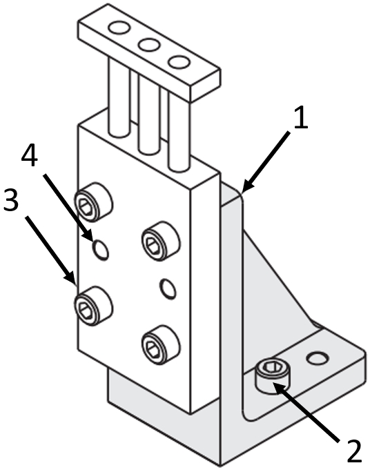
Application example: angle bracket with guide cylinder
(1) Angle bracket, (2) Hexagon socket screw, (3) Air cylinder, (4) Dowel pin
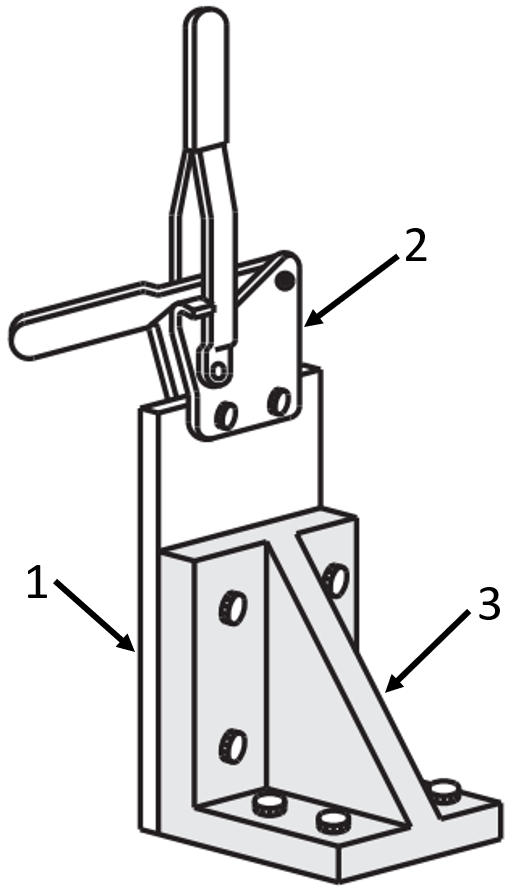
Application example: angle bracket with push-pull toggle clamps
(1) Mounting plate, (2) push-pull toggle clamps, (3) angle bracket
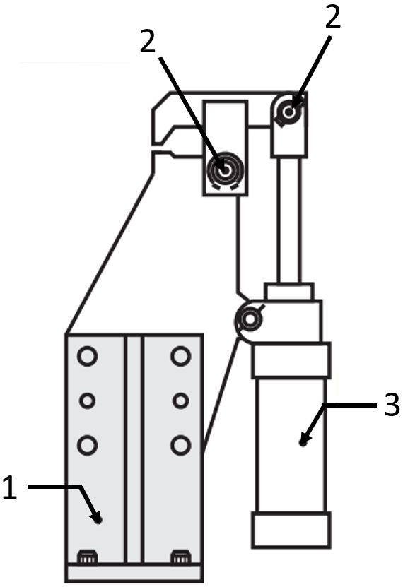
Application example: angle bracket with cylinder
(1) Angle bracket, (2) hinge bolts, (3) cylinder
Industrial Applications




Basic information
| Strength | Standard (Cast) |
|---|
Configure
Basic Attributes
-
Hole Machining
- Through Hole
- Through Holes and Dowel Holes
-
Surface Treatment
- Electroless Nickel Plating
- Black Oxide
- Primer Paint (Gray)
- Not Provided
-
Height H(mm)
-
Dimension A(mm)
-
B(mm)
-
F(mm)
-
G(mm)
-
X(mm)
-
Y(mm)
-
Type
- AIKDF
- AIKF
- BIKDF
- BIKF
- IKDF
- IKF
- MIKDF
- MIKF
-
Material
- Steel
- Aluminum
-
Filter by CAD data type
- 2D
- 3D
Filter by standard shipping days
-
- All
- 13 Days or Less
Optional Attributes
- The specifications and dimensions of some parts may not be fully covered. For exact details, refer to manufacturer catalogs .
Frequently Asked Questions (FAQ)
-
Question:
What do you use the angle brackets for?
-
Answer:
An angle bracket can be used for a wide variety of applications in mechanical engineering. In general, they are used to connect or fix different components and devices. Angle brackets are manufactured very precisely with their perpendicularity compared to conventional mounting angles. Therefore, angle brackets are also frequently used to accommodate pneumatic cylinders, positioning stages, and stages. Another benefit of the angle bracket is its high rigidity due to the additional stiffening rib. This provides the angle bracket with a very good stability. Therefore, it can absorb heavier loads compared to normal angles.
-
Question:
What are the different types of steel on angle brackets?
-
Answer:
MISUMI offers the massive and precise angle bracket in two different types of steel. The MISUMI product range offers the material EN 1.0038 equivalent, which is also known as S235JR. This material is often used for extruded profiles. This shows good ductility, toughness and plasticity. As a further material, the range contains the EN-JL 1040 equivalent. This is grey cast iron with slat graphite, which has very good workability and is often used in machine tools.
-
Question:
What coatings are available for angle brackets made of steel?
-
Answer:
Our angle brackets are available untreated for further processing. To protect against corrosion, the angle bracket can be burnished, primed (grey) and nickel-plated.
-
Question:
What are the advantages of aluminum brackets?
-
Answer:
Aluminum brackets and aluminum angle brackets have a low weight and are therefore suitable for weight reduction. Aluminum, on the other hand, has a high strength in relation to heavier materials. As a result, these are also suitable for high loads. Another advantage is that aluminum does not require further corrosion protection. In addition, aluminum has a low thermal expansion, which gives it dimensional stability in case of temperature fluctuations.
Complementary Products
Tech Support
- Technical Support
- Tel:+49 69 668173-0 / FAX:+49 69 668173-360
- Technical Inquiry

![[Precision] X-Axis / Cross Roller](http://content.misumi-ec.com/image/upload/f_auto,t_product_recommend_a/v1/p/jp/product/series/110300196460/110300196460_001.jpg)
