- Shaft Diameter(mm)
- 6
- 8
- 10
- 12
- 13
- 15
- 16
- 17
- 18
- 20
- 22
- 25
- 30
- Material
- Surface Treatment
- Material
- Thread Length Specifying Method
- M (Coarse)
- 6
- 8
- 10
- 12
- 16
- 20
- Pin Shape
- Thread Length N(mm)
- 9
- 12
- 15
- 18
- 24
- 30
- F(mm)[5–150/1mm jedn.]
- G(mm)[5–20/1mm jedn.]
- Thread Dia. Selection [MA]
- 3
- 4
- 5
- 6
- 8
- 10
- 12
- 16
- 20
- Thread Length [N](mm)[6–40/1mm jedn.]
- Y(mm)[5–75/1mm jedn.]
- CAD
- 2D
- 3D
- Szacowane dni wysyłki
- Wszystko
- W ciągu 3 dni robocze
- W ciągu 4 dni robocze
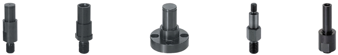
Cantilever Shafts / heel selectable / external thread, internal thread / external hexagon

Numer części:
.Rysunek konturowy i tabela specyfikacji

| Standard | Stepped | [M] Material | [S] Surface treatment | ||
| Thread Length Fixed | Thread Length Configurable | Thread Length Fixed | Thread Length Configurable | ||
| FXKB | FXNKB | FXLB | FXNLB | EN 1.1191 Equiv. | Black Oxide |
| PFXKB | PFXNKB | PFXLB | PFXNLB | Electroless Nickel Plating | |
| SFXKB | SFXNKB | SFXLB | SFXNLB | EN 1.4301 Equiv. | — |
Specification Table
| Part Number | — | Y | — | F | — | G | — | N | — | MA |
| FXKB20A FXNKB12 SF−SFXKB10 | — — — | 20 15 20 | — — — | F12 F21 F12 | — — — | G8 G5 G8 | — | N14 | — — — | MA10 MA6 MA4 |
| D Tolerance (g6) | |
| 6 | −0.004 −0.012 |
| 8·10 | −0.005 −0.014 |
| 12 to 18 | −0.006 −0.017 |
| 20 to 30 | −0.007 −0.020 |
| Part Number | D | 1 mm Increments | N | MA (Coarse) Selection | P | M (Coarse) | V (Stepped Type only) | B | (C) | |||||||||||||
| Type | No. | Y | F | G | Thread Length Fixed | Thread Length Configurable | ||||||||||||||||
| Standard Thread Length Fixed FXKB PFXKB SFXKB Stepped Thread Length Fixed FXLB PFXLB SFXLB | Configurable FXNKB PFXNKB SFXNKB Configurable FXNLB PFXNLB SFXNLB | 6 | 6 | 5 to 60 | 5 to 100 | 5 to 10 | 9 | 6 to 12 | 3 | 6 | M 6 | 8 | 10 | 11.5 | ||||||||
| 8 | 8 | 12 | 8 to 16 | 4 | 8 | M 8 | 10 | 12 | 13.9 | |||||||||||||
| 10 | 10 | 15 | 10 to 20 | 4 | 5 | 6 | 10 | M10 | 13 | 14 | 16.2 | |||||||||||
| 12 | 12 | 10 to 120 | 5 to 15 | 18 | 12 to 24 | 5 | 6 | 8 | 12 | M12 | 15 | 17 | 19.6 | |||||||||
| 13 | 13 | 16 | ||||||||||||||||||||
| 15 | 15 | 6 | 8 | 10 | 18 | 19 | 21.9 | |||||||||||||||
| 16 | 16 | 19 | ||||||||||||||||||||
| 17 | 17 | 5 to 75 | 5 to 20 | 20 | 22 | 27.5 | ||||||||||||||||
| 18 | 18 | 21 | 24 | 27.7 | ||||||||||||||||||
| 20 | 20 | 30 | 20 to 40 | 6 | 8 | 10 | 12 | 20 | M20 | 24 | 27 | 31.2 | ||||||||||
| 20 A | 16 | M16 | ||||||||||||||||||||
| 22 | 22 | 20 | M20 | 26 | 27 | 31.2 | ||||||||||||||||
| 22 A | 16 | M16 | ||||||||||||||||||||
| 25 | 25 | 8 | 10 | 12 | 16 | 20 | M20 | 29 | 30 | 34.6 | ||||||||||||
| 25 A | 16 | M16 | ||||||||||||||||||||
| 30 | 30 | 8 | 10 | 12 | 16 | 20 | 20 | M20 | 34 | 36 | 41.6 | |||||||||||
| 30 A | 16 | M16 | ||||||||||||||||||||
| MA | Y+F |
| M 3 | Y+F ≥ 11.5 |
| M 4 | Y+F ≥ 14.0 |
| M 5 | Y+F ≥ 16.2 |
| M 6 | Y+F ≥ 18.5 |
| M 8 | Y+F ≥ 23.5 |
| M10 | Y+F ≥ 28.5 |
| M12 | Y+F ≥ 35.5 |
| M16 | Y+F ≥ 45.0 |
| M20 | Y+F ≥ 55.0 |
Alterations
| Part Number | — | Y | — | F | — | G | — | N | — | MA | — | (YKC·SC·MTC·SET) |
| FXLB12 | — | 27 | — | F15 | — | G7 | — | MA6 | — | MTC |
| Alterations | Retaining Ring Set | Y Dimension Tolerance | Wrench Flats | Tapped Hole | ||||||||||||||||||||||||||||||||||||||||||||
 |  |  | ||||||||||||||||||||||||||||||||||||||||||||||
| Code | SET | YKC | SC | MTC | ||||||||||||||||||||||||||||||||||||||||||||
| Spec. | Retaining Ring applicable to each shaft diameter is included. Ordering Code SET Applicable to Retaining Ring Type. Retaining Ring Shape No. = 6 to 8: Retaining Ring Type E No. 10 to 30A: Retaining Ring Type C Retaining Ring Material
| Changes Y dimension tolerance to ±0.05. Changes Y dimension tolerance to ± 0.05. [!] Applicable to all types Ordering Code YKC | An alteration of wrench flats can be made for a slot hole guide. [!] Applicable to all types Ordering Code SC [!] P (wrench flats) tolerance is | An alteration of a tapped hole made for shaft push/pull. Allows combined use of AJST, AJKC . (Configurable dimension Y is limited. Refer to the table below.) Ordering Code MTC
 [!] When combined with SC, add 3 mm to dimension Y. | ||||||||||||||||||||||||||||||||||||||||||||
Lista numerów części
| Numer części |
|---|
Cena jednostkowa (bez VAT)(Cena jednostkowa z podatkiem) | Standardowa data wysyłki |
|---|
- ( - ) | 4 dni robocze |
- ( - ) | 4 dni robocze |
- ( - ) | 4 dni robocze |
- ( - ) | 4 dni robocze |
- ( - ) | 4 dni robocze |
- ( - ) | 4 dni robocze |
- ( - ) | 4 dni robocze |
- ( - ) | 4 dni robocze |
- ( - ) | 4 dni robocze |
- ( - ) | 4 dni robocze |
- ( - ) | 4 dni robocze |
- ( - ) | 4 dni robocze |
- ( - ) | 4 dni robocze |
- ( - ) | 4 dni robocze |
- ( - ) | 4 dni robocze |
- ( - ) | 4 dni robocze |
- ( - ) | 4 dni robocze |
- ( - ) | 4 dni robocze |
- ( - ) | 4 dni robocze |
- ( - ) | 4 dni robocze |
- ( - ) | 4 dni robocze |
- ( - ) | 4 dni robocze |
- ( - ) | 4 dni robocze |
- ( - ) | 4 dni robocze |
- ( - ) | 4 dni robocze |
- ( - ) | 4 dni robocze |
- ( - ) | 4 dni robocze |
- ( - ) | 4 dni robocze |
- ( - ) | 4 dni robocze |
- ( - ) | 4 dni robocze |
- ( - ) | 4 dni robocze |
- ( - ) | 4 dni robocze |
- ( - ) | 4 dni robocze |
- ( - ) | 4 dni robocze |
- ( - ) | 4 dni robocze |
- ( - ) | 4 dni robocze |
- ( - ) | 4 dni robocze |
- ( - ) | 4 dni robocze |
- ( - ) | 4 dni robocze |
- ( - ) | 4 dni robocze |
- ( - ) | 4 dni robocze |
- ( - ) | 4 dni robocze |
- ( - ) | 4 dni robocze |
- ( - ) | 4 dni robocze |
- ( - ) | 4 dni robocze |
- ( - ) | 4 dni robocze |
- ( - ) | 4 dni robocze |
- ( - ) | 4 dni robocze |
- ( - ) | 4 dni robocze |
- ( - ) | 4 dni robocze |
- ( - ) | 4 dni robocze |
- ( - ) | 4 dni robocze |
- ( - ) | 4 dni robocze |
- ( - ) | 4 dni robocze |
- ( - ) | 4 dni robocze |
- ( - ) | 4 dni robocze |
- ( - ) | 4 dni robocze |
- ( - ) | 4 dni robocze |
- ( - ) | 4 dni robocze |
- ( - ) | 4 dni robocze |
Szczegółowe informacje
Kontury i specyfikacja
General Information - Cantilever Shafts
Selection details of cantilever shafts/cantilever bolts
- Material: stainless steel, steel, tempered steel
- Coatings: untreated, burnished, nickel-plated
- Fastening: retaining ring, internal thread, external thread, centring collar with internal thread
- ISO tolerance: g6
- Thread: M3 to M20
- Straightness: up to 0.02 mm
- Roundness: up to 0.02 mm
- Shaft diameter: 3 to 50 mm
-Length: 3 to 150 mm
Description/Basics
They are basically used to support rotary rolling bearings. The support position can be precisely determined by its configurability. The different mounting variants offer a compact and space-saving option for many applications, e.g., to accommodate ball bearings.
Cantilever shafts with collar or shoulder are well suited to determine a support position. The collar serves as a contact surface for the bearing inner wheel. Since the collar of the cantilever shaft can be configured, individual adaptation is simple. The variant [YKC] offers the option of a particularly precise axle bolt with collar, with a length tolerance of +/- 0.05 mm. Due to this property, an additional washers can be omitted with this cantilever shaft.
The cantilever shafts are also available with double collars or double offset. These are suitable for idler pulleys with a small diameter, since the reduced additional shoulder can prevent grinding of the idler pulley.
Cantilever shafts with retaining ring groove (groove) are the most commonly used bearing bolts, because the retaining rings allows for easy assembly and disassembly. The cantilever shafts including the retaining ring can be delivered with the [SET] option. We also offer threaded cantilever shafts that can be selected with external threads or internal threads.
As a special form, our product range offers cantilever shafts with flanges. Due to the large contact surface, higher forces can be absorbed and distributed more evenly compared to conventional cantilever shafts. If you want to attach ball bearings that also have to withstand axial forces, for example, the cantilever shaft with flange offers a good solution. Due to its versatility, the cantilever shaft with flange can be used for a wide variety of design solutions.
Our product range includes various drives for assembly. From the typical hexagon to spanner flat, to additional cross holes with threads that can be used for example for a tension application for clamping devices.
The field of application of cantilever shafts in mechanical engineering is fundamentally very large. They are utilised in synchronous drives, chain transmission or in various tasks in device construction
Bearing pins can be used in combination with ball bearings or plain bearing bushings. Among other things, you can select roller idlers (with rolling bearings), idler pulleys or timing pulleys. As an alternative for limited installation space, we offer cam rollers, which come assembled and ready to install consisting of cantilever shafts and rolling bearings.
Bearing pins are also often used in conjunction with links to ensure different movement sequences.
For high loads, we offer the cantilever shafts made of heat-treated steel, which are produced to be wear-resistant and durable with a hardness of up to 40HRC.
Our product range also offers suitable screws and nuts for fastening cantilever shafts.
Application Examples - Cantilever Shafts
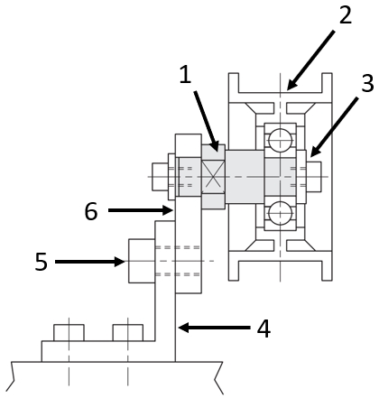
Application example: deflection roller
(1) Cantilever shaft, (2) Idler pulley, (3) Spacer washer, (4) Mounting angle, (5) Screw, (6) Mounting plate
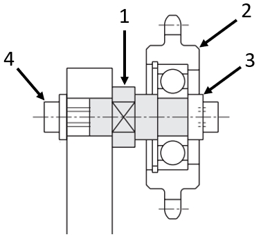
Application example: chain idlers
(1) Cantilever shafts, (2) Chain idlers, (3) Spacer washer, (4) Screw
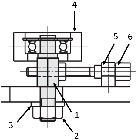
Application example: idler pulley
(1) Cantilever shaft, (2) Locknut, (3) Washer, (4) Idler pulley, (5) Threaded stopper block, (6) Adjusting screw
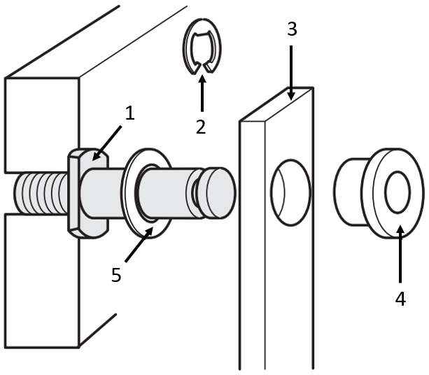
Application example: link with plain bearing bushing
(1) Cantilever shaft, (2) Retaining ring, (3) Links, (4) Plain bearing bushing, (5) Thrust washer
Industrial Applications


