- Stan magazynowy
- Pokaż tylko pozycje magazynowe
- Hole Dia. D(mm)
- 8
- 10
- 12
- 13
- 16
- 20
- 25
- 30
- Material
- Steel
- EN 1.1191 Equiv.
- Stainless Steel
- EN 1.4301 Equiv.
- Aluminum
- EN AC-51300 Equiv.
- Surface Treatment
- Height H(mm)
- 15
- 20
- 25
- 30
- Type
- CAD
- 2D
- 3D
- Szacowane dni wysyłki
- Wszystko
- Możliwa wysyłka tego samego dnia
- W ciągu 5 dni robocze
- W ciągu 9 dni robocze
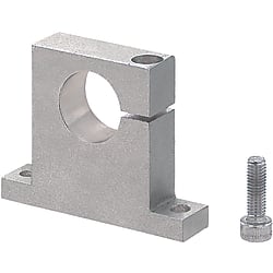
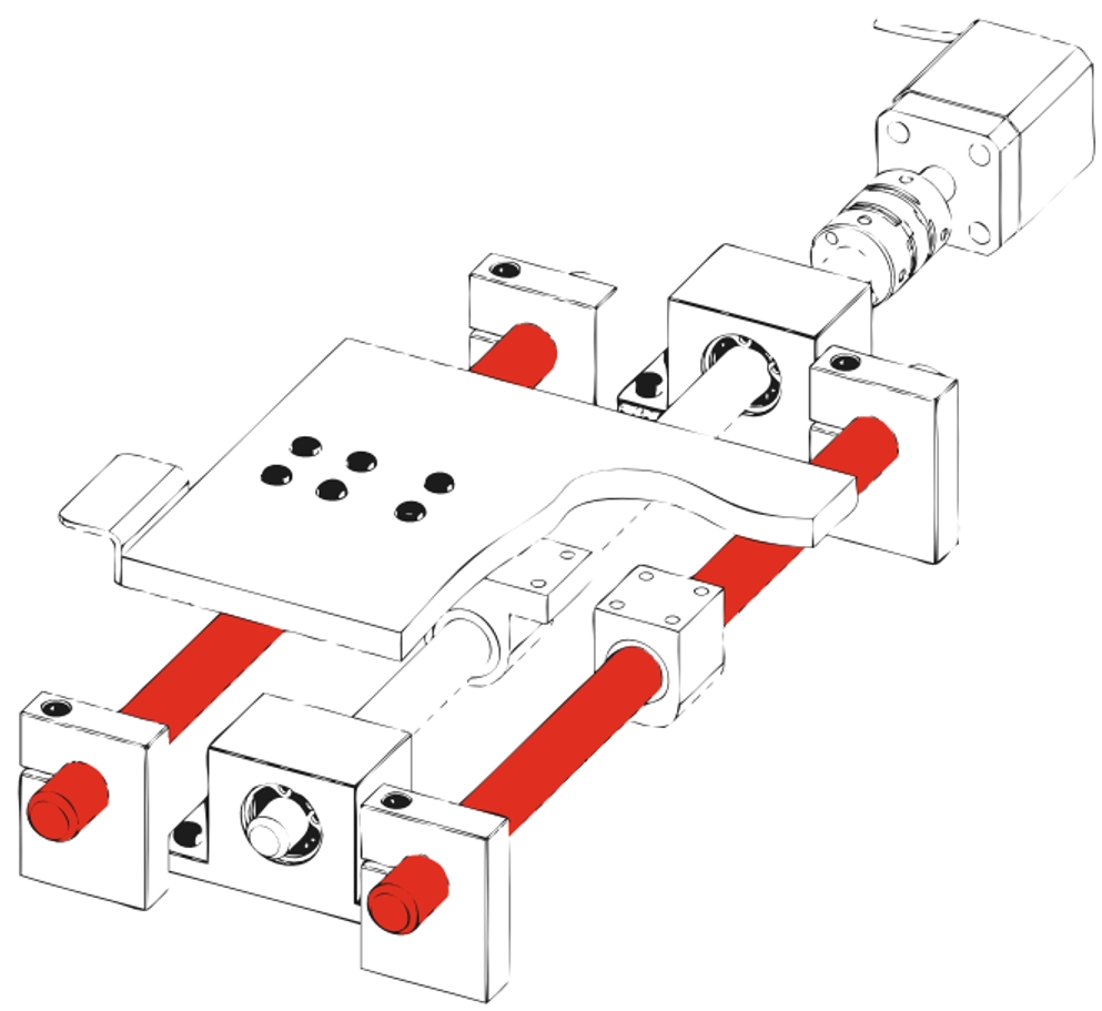
Shaft holders / T-shape / slotted sideways


Numer części:
.Rysunek konturowy i tabela specyfikacji

[!] Slit is machined after the mounting hole D is bored to H7 tolerance. The tolerance may become H8 or so depending on the machining condition.
[!] Pilot hole for tapped hole M may be through.
[!] There may be no cast characters.
| Type | [M] Material | [S] Surface Treatment | [A]Accessory |
| SHTCT | EN 1.1191 Equiv. | Black Oxide | Hex Socket Head Cap Screw 1 pc. |
| SHTCM | Electroless Nickel Plating | Hex Socket Head Cap Screw 1 pc. (Stainless Steel) | |
| SHTCS | EN 1.4301 Equiv. | — | |
| SHTCA | EN AC−51300 Equiv. | Clear Anodize |
Specification Table
| Part Number | ||
[oil] | SHTCT3030 SHTCS2025 SF−SHTCS2530 | |
| Part Number | D | H | L | H1 | T | L1 | d | L2 | A | S | E | C | B1 | B2 | B3 | Tightening Screw M | Mass g | |
| Type | No. | |||||||||||||||||
| SHTCT SHTCM SHTCS SHTCA | 815 | 8 | 15 | 52 | 22 | 12 | 40 | 5.5 | 28 | 26 | 6 | 9 | 2 | 14 | 8 | 2 | M4 | 61 (21) |
| 1020 | 10 | 20 | 54 | 29 | 42 | 30 | 27 | 10 | 81 (28) | |||||||||
| 1220 | 12 | 56 | 31 | 44 | 32 | 28 | 11 | 90 (31) | ||||||||||
| 1320 | 13 | 87 (30) | ||||||||||||||||
| 1625 | 16 | 25 | 58 | 37 | 46 | 34 | 29 | 12 | 107 (37) | |||||||||
| 2025 | 20 | 79 | 40 | 16 | 64 | 6.5 | 49 | 39.5 | 8 | 17 | M6 | 220 (76) | ||||||
| 2030 | 30 | 45 | 254 (88) | |||||||||||||||
| 2530 | 25 | 48 | 18 | 248 (86) | ||||||||||||||
| 3030 | 30 | 102 | 51 | 20 | 82 | 9 | 62 | 51 | 10 | 22 | 3 | M8 | 477 (165) | |||||
Lista numerów części
Cena jednostkowa (bez VAT)(Cena jednostkowa z podatkiem) | Standardowa data wysyłki |
|---|
9.76 € ( 11.61 € ) | 5 dni robocze |
10.26 € ( 12.21 € ) | 9 dni robocze |
12.82 € ( 15.26 € ) | 5 dni robocze |
10.56 € ( 12.57 € ) | 9 dni robocze |
11.44 € ( 13.61 € ) | 9 dni robocze |
12.52 € ( 14.90 € ) | 5 dni robocze |
13.63 € ( 16.22 € ) | 5 dni robocze |
15.41 € ( 18.34 € ) | 9 dni robocze |
9.68 € ( 11.52 € ) | Towar dostępny w magazynie – 1 dzień roboczyDostępne z opcją wysyłki tego samego dnia |
Szczegółowe informacje
Podstawowe informacje
Kontury i specyfikacja
Shaft Holder Selection Details
- Material: aluminum, stainless steel, steel
- Coatings: uncoated, burnished, nickel-plated, clear anodized, black anodized
- ISO tolerances: H7
- Perpendicularity: 0.02 mm
- Inside diameter: 3 to 50 mm
- Shaft fastening: clamping screw, with keyway, slotted clamping, with clamping lever, two-parts, with hinge
- Basic shapes: round flange, guided round flange, compact flange, square flange, T-shape, L-shape, block shape, round
- Shaft holder fastening: through hole, with dowel pin bore, with countersunk bore, internal thread
Description/Basics
Shaft holders serve as fastener between a rigid shaft (axis) and an application.
The basic task of shaft holders, also known as shaft supports, is the horizontal or vertical mounting and fastening of axles, linear shafts and rotary shafts.
Unlike bearings with housing, shaft holders do not have a ball bearing. Shaft holders are used to fix rigid axles and shafts on which rotating or linearly moving components are located. This means that shaft holders are used in rotary and linear applications.

Application example of an axle support with linear shaft
Shaft holders primarily transfer compressive loads and tensile loads from the axis to the base of the application. Depending on the application and the load applied, the wall thickness of the shaft mount must be selected accordingly.
The shaft receiver of the shaft holder is provided by default with an H7 or 0 / +0.1 fitting bore. Therefore, the ISO shaft tolerances g6, f8 and h5 are suitable are suitable for connecting the shaft. The MISUMI shaft holders can be configured via the option [HC] in the shaft height in up to 0.1 mm increments. This allows the shaft position to be precisely aligned to the required height of the shaft.
With the option [MB], the set screw of the shaft holder can be added to the variant with clamping screw. You can see whether this option is available in the Section ‘Additional Options/Changes’. Alternatively, MISUMI also offers set screws individually in different variations.
Shaft fastener
MISUMI offers various clamping options for the shaft holders.
Shaft holder with set screw
The standard version of the shaft mount is a shaft holder with clamping screw. This method of fixing the shaft is clamped in the shaft holder with a clamping screw (set screw). In this type of fixing, the shaft is generally provided with a flat surface, because this increases the clamping surface, which is particularly advantageous for flat set screws. Another advantage of the flat surface is that the running surface of the shaft is not deformed by the clamping pressure of the set screw. Therefore, it reduces the risk of tilting during the disassembly of the shaft.
Another option for protecting the running surface of the shaft in the shaft holder is the use of a set screw with tappet or a pressure piece made of a soft material (e.g., plastic or brass).
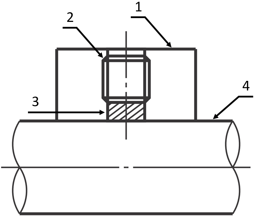
Application example: shaft holder with set screw and pressure piece – (1) Shaft holder, (2) Shaft holder, (3) Pressure piece, (4) Linear shaft
Shaft holder with slot
A further variant of shaft mounting represents fastening through a shaft holder with a clamping slot. The main advantage of shaft blocks with slotted clamping is that almost the entire contact surface of the shaft holder is used for clamping the shaft. The result is a uniform distribution of the clamping force. This means that the shaft can be connected with increased clamping force without damaging it. MISUMI offers shaft brackets with slot clamps with vertical and horizontal slots.

Drawing: shaft block with slot clamping
Shaft holder with slot and clamping lever
In applications where the shafts often have to be adjusted in axial direction, a shaft holder with clamping lever can be helpful. This shaft holder is structurally the same as a shaft holder with a clamping slot. However, a clamping lever is installed on this shaft holder instead of the clamping screw, which builds up the clamping pressure. Therefore, it can be readjusted without the requirement of an additional tool.

Drawing: shaft holder with clamping lever
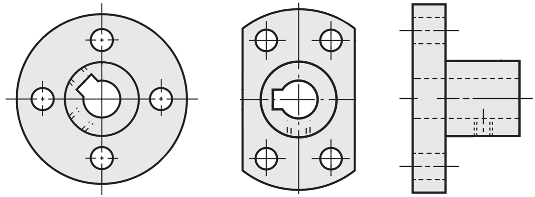
Shaft holder with flange
For applications with limited installation space, a round shaft flange can be a suitable variant. A shaft flange is often used in vertical stroke applications. This is a separate design at MISUMI. It can be configured with slotted clamping and clamping screw.

Drawing: shaft flange with slotted clamping and clamping screw
Shaft holder with flange and keyway
The shaft holder with keyway is a special form of the shaft holder at MISUMI. This special form extends the range of application of the shaft holders and has a variety of special functions compared to a standard shaft holder.
Drawing: keyway shaft flange
Shaft holder with flange for rear mounting
Another special form of the shaft holder at MISUMI is the shaft flange for rear mounting of the shaft. With this shaft holder, the back of the shaft flange has a counterbore for a cylinder head screw that secures the shaft. For this purpose, it is necessary that the shaft is provided with an internal thread at the shaft end. This method of fixing does not require any further clamping of the shaft.

Drawing: rear mount shaft holder
Round shaft holder
The round shaft holder is the combination of a compact version of a shaft flange and a shaft collar. The round shaft bracket has mounting holes on the front and slotted clamps. In contrast to the flanged shaft holder, the outer mounting flange is omitted for the round shaft holder. Therefore, it requires less space than the conventional shaft flange. As a result, it is better suited for applications with limited space.
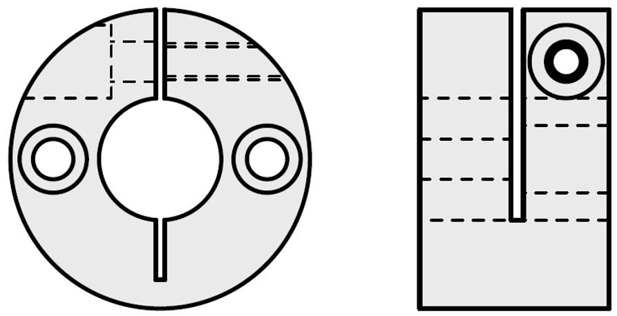
Drawing: round and compact shaft holder
Two-part shaft holder with slot
For shafts that require frequent maintenance, an application can be equipped with a two-part shaft holder. With a two-part shaft holder, the upper part of the shaft holder is fixed in place with two screws and can be easily assembled and disassembled. During maintenance, the previously adjusted shaft holder can remain in its position and do not need to be readjusted. These shaft holders have two opposite slots and secure the shaft via the slot clamp. The advantages of slot clamping are that almost the entire contact surface of the shaft holder is used for clamping the shaft. This causes a uniform distribution of force, which allows the shaft to be fixed with increased clamping force without damaging it.

Drawing: two-part shaft holder, two-part shaft flange
Two-part shaft holder with slot and hinge
Another rare version of two-part shaft brackets is the hinged shaft holder. These shaft holders simplify the assembly and disassembly of the shaft compared to common shaft holders. Another advantage of this variant over the conventional two-part shaft holder is that the upper part remains fixed to the shaft holder in loosened state and is thus secured against loss.

Drawing: shaft holder with hinge
As an alternative to a shaft holder, a column base can also be used. These offer extremely precise positioning due to their precise concentricity. For shafts that need to be mounted for rotary movement, MISUMI offers shaft holders with integrated ball bearings (bearings with housing).
Areas of Application
Since each shaft requires a connecting element for support and fastening, shaft holders are necessary connecting means for a variety of applications. MISUMI has a wide product range of shaft holders to meet a wide variety of requirements. MISUMI offers the right axle holder depending on the application and shaft alignment. Through the various mounting options, as well as selectable geometries, diameters, configurable shaft heights and shaft fastening types, MISUMI shaft supports offer a wide range of possible uses and individual utilization for mechanical engineering and plant engineering across many industrial sectors.
Materials
MISUMI shaft holders are available in aluminum, steel, and stainless steel. Shaft holders can be cast or machined from these materials.
Dimensions

Drawing: axle holder with chamfered round flange

Drawing: round shaft flange

Drawing: shaft flange with guided round flange

Drawing: round shaft holder

Drawing: shaft holder in T-shape

Drawing: shaft holder in L-shape

Drawing: shaft holder in block form
Instructions for use
MISUMI offers shaft holders in very small and low block shapes for very limited installation spaces. Thanks to the lateral mounting holes, a shaft to be mounted very low in an application. These shaft holders allow a shaft height of approx. 5 mm, depending on the shaft diameter.

Comparison of a standard and low installation height shaft holder
(1) Shaft holder in high block shape, (2) Shaft holder in block shape, (3) Shaft holder in T-shape, (4) Shaft holder in low T-shape, (5) Low two-part shaft holder
Installation Information

Drawing: shaft flange with through-holes

Drawing: shaft holder with counterbore

Drawing: shaft flange with through-hole and dowel pin holes

Drawing: guided shaft flange with through-holes

Drawing: shaft flange drawing with continuous female thread

Drawing: female-threaded shaft support

Application example: shaft support in T-shape and linear shafts

Application example: shaft flange

Application example: shaft holder with guide flange
Application example: block-shaped shaft support with slot clamping
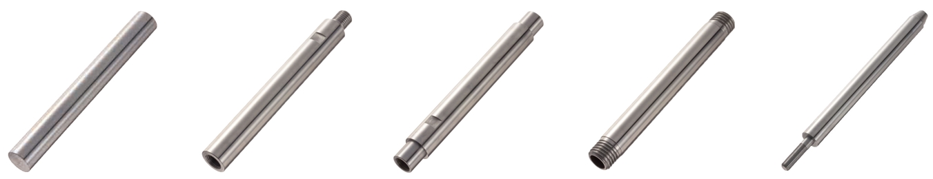
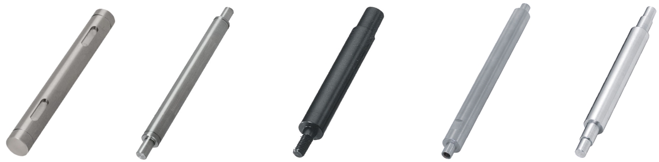

Dowel Pins, Spring Pins, Stepped Pins


