- Dimensions when open(mm)
- 12
- Dimensions when closed(mm)
- 0
- Gripping Force (when 0.5Mpa at opening)(N)
- 48
- Gripping Force (when 0.5Mpa at closing)(N)
- 48
- Additional Function
- Stroke Adjustment Mechanism
- Cylinder internal diameter(mm)
- 12
- Body options
- Auto switch
- Number of switches
- Lead wire length
- Stroke(mm)
- 12
- Made to order specifications
- Connector type for gripper opening/closing
- Stroke adjustment width(mm)
- 8
- Type
- CAD
- 2D
- 3D
- Szacowane dni wysyłki
- Wszystko
- W ciągu 26 dni robocze
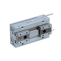
MHF2, Air Gripper, 2 Finger, Low Profile (MHF2-12D-X83B1)


Informacje o produkcie
MHF2 Series Low Profile Air Gripper Specifications

Double acting, internal grip JIS symbol

Double acting, external grip JIS symbol

Body option: axial ported (Nil) external appearance

Body option: side ported (R) external appearance
| Fluid | Air | |
|---|---|---|
| Operating pressure | ø8 (diameter 8 mm): 0.15 to 0.7 MPa | |
| ø12 to 20 (diameter 12 to 20 mm): 0.1 to 0.7 MPa | ||
| Ambient and fluid temperature | -10°C to +60℃ (no freezing) | |
| Repeatability | ±0.05 mm*1 | |
| Maximum operating frequency | Short stroke | 120 c.p.m. |
| Middle stroke | 120 c.p.m. | |
| Long stroke | 60 c.p.m. | |
| Lubrication | Non-lube | |
| Action | Double acting | |
| Auto switch (option)*2 | Solid state auto switch (3-wire, 2-wire) | |
*1 Value when no unbalanced load is applied to the finger. If the finger is subjected to an unbalanced load, the backlash of the rack pinion can be up to ±0.15 mm.
*2 See the manufacturer's catalog for detailed specifications of auto switches.
Model
| Action | Model | Cylinder bore (mm) | Gripping force*1 | Opening/closing stroke (Both sides) mm | Weight*2 g | Unobstructed capacity (cm3) | |
|---|---|---|---|---|---|---|---|
| Effective gripping force per finger N | Finger opening side | Finger closed side | |||||
| Double acting | MHF2-8D | 8 | 19 | 8 | 65 | 0.7 | 0.6 |
| MHF2-8D1 | 16 | 85 | 1.1 | 1.0 | |||
| MHF2-8D2 | 32 | 120 | 2.0 | 1.9 | |||
| MHF2-12D | 12 | 48 | 12 | 155 | 1.9 | 1.6 | |
| MHF2-12D1 | 24 | 190 | 3.3 | 3.0 | |||
| MHF2-12D2 | 48 | 275 | 6.1 | 5.8 | |||
| MHF2-16D | 16 | 90 | 16 | 350 | 4.9 | 4.1 | |
| MHF2-16D1 | 32 | 445 | 8.2 | 7.4 | |||
| MHF2-16D2 | 64 | 650 | 14.9 | 14.0 | |||
| MHF2-20D | 20 | 141 | 20 | 645 | 8.7 | 7.3 | |
| MHF2-20D1 | 40 | 850 | 15.1 | 13.7 | |||
| MHF2-20D2 | 80 | 1,225 | 28.0 | 26.6 | |||
*1 Values based on pressure of 0.5 MPa, gripping point L = 20 mm.
*2 Values above do not include auto switch weight.
Structure drawing

MHF2-8D, MHF2-8D1 structure drawing

MHF2-8D2 structure drawing
| No. | Description | Material | Note |
|---|---|---|---|
| 1 | Body | Aluminum alloy | Hard anodized |
| 2 | Piston | Stainless steel | - |
| 3 | Joint | Stainless steel | Heat treatment |
| 4 | Guide rail | Stainless steel | Heat treatment |
| 5 | Finger | Stainless steel | Heat treatment |
| 6 | Roller stopper | Stainless steel | - |
| 7 | Pinion | Carbon steel | Nitriding |
| 8 | Cap A | Aluminum alloy | Clear anodized |
| 9 | Cap B | Aluminum alloy | Clear anodized |
| 10 | Cap C | Aluminum alloy | Clear anodized |
| No. | Description | Material | Note |
|---|---|---|---|
| 11 | Head bumper | Urethane rubber | - |
| 12 | Clip | Stainless steel wire | - |
| 13 | Rack | Stainless steel | Nitriding |
| 14 | Magnet | - | Nickel plated |
| 15 | Steel ball | High carbon chrome bearing steel | - |
| 16 | Wear ring | Synthetic resin | - |
| 17 | Roller | High carbon chrome bearing steel | - |
| 18 | Needle roller | High carbon chrome bearing steel | - |
| 19 | Parallel pin | Stainless steel | - |
| 20 | Piston seal | NBR | - |
| 21 | Gasket | NBR | - |

MHF2-12D□ to 20D□ structure drawing
| No. | Description | Material | Note |
|---|---|---|---|
| 1 | Body | Aluminum alloy | Hard anodized |
| 2 | Piston | Aluminum alloy | Clear anodized |
| 3 | Joint | Stainless steel | Heat treatment |
| 4 | Guide rail | Stainless steel | Heat treatment |
| 5 | Finger | Stainless steel | Heat treatment |
| 6 | Roller stopper | Stainless steel | - |
| 7 | Pinion | Carbon steel | Nitriding |
| 8 | Cap A | Aluminum alloy | Clear anodized |
| 9 | Cap B | Aluminum alloy | Clear anodized |
| 10 | Cap C | Aluminum alloy | Clear anodized |
| 11 | Head bumper | Urethane rubber | - |
| 12 | Rack | Stainless steel | Nitriding |
| 13 | Magnet | - | Nickel plated |
| 14 | Steel ball | High carbon chrome bearing steel | - |
| 15 | Wear ring | Synthetic resin | - |
| 16 | ø12 (diameter 12 mm): Roller | High carbon chrome bearing steel | - |
| ø16 to 20 (diameter 16 to 20 mm): Parallel pin | Stainless steel | - | |
| 17 | Needle roller | High carbon chrome bearing steel | - |
| 18 | ø12 (diameter 12 mm): R-shaped retaining ring | Carbon steel | Phosphate coated |
| ø16 to 20 (diameter 16 to 20 mm): Type C retaining ring | |||
| 19 | Parallel pin | Stainless steel | - |
| 20 | Piston seal | NBR | - |
| 21 | Gasket | NBR | - |
| 22 | Gasket | NBR | - |
External dimensional drawing
(Unit: mm)

MHF2-8D dimensional drawing
*If mounting holes are used, use the hex socket head cap screw (accessory).
(Unit: mm)

MHF2-8D A detail dimensional drawing
(Unit: mm)

MHF2-8D auto switch mounting groove dimensional drawing
Precautions
- *Be sure to read the product precautions in the manufacturer's catalog before use.
- *See the manufacturer's catalog for information other than the above.
Szczegółowe informacje
Podstawowe informacje
[Features]
· Low profile: Height is approximately 1/3 smaller (compared to product with equivalent gripping force from the MHZ2 Series).
· Contributes to device space saving measures.
· Reduces bending moments.
· Operates smoothly, providing improved accuracy.
· The stroke length can be selected.
& nbsp3 standard stroke lengths (short, middle and length) are available for each bore size.
& nbspYou can select the optimal stroke for each workpiece.
· Improved mounting repeatability.
· Piping from either direction.
· Easy positioning for mounting attachments.
· Wiring and piping can be centralized.
· High degree of mounting flexibility.
& nbspBracket not required.
& nbspCan help keep mounting height to a minimum.
· A compact design in which a large amount of gripping force is provided through the use of a double piston mechanism.
Przestroga
- Refer to the catalog for details on product specifications.
- Product images may be representative. Refer to the manufacturer's catalog for details.