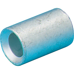
Bare Crimp Terminal Superposition Model Crimp Ring【100 szt.】
Specyfikacja produktu
Specifications
| 1-pack | 100-piece Pack |
More Information
External Dimensions Table and Applicable Wires
| Model | External Dimensions (Unit: mm) | Compatible Electric Wire Size | Weight (g) | Compatible Tool | ||||
| A | B | C | D | Stranded Wire (mm2) | AWG | |||
| P-0.5 | 7.5 | 1.3 | 2.3 | 0.50 | 0.2 ~ 0.5 | 24 ~ 20 | 0.183 | DS031 |
| P-1.25 | 8.0 | 1.7 | 3.3 | 0.75 | 0.25 ~ 1.65 | 22 ~ 16 | 0.442 | NH-1 |
| P-2 | 2.3 | 4.1 | 0.80 | 1.04 ~ 2.63 | 16 ~ 14 | 0.588 | ||
| P-5.5 | 8.5 | 3.4 | 5.4 | 1.00 | 2.63 ~ 6.64 | 12 ~ 10 | 1.070 | |
Szczegółowe informacje
Podstawowe informacje
Superposition crimp model crimping ring made by Japanese manufacturers. JIS, CSA standard products. 1 pack contains 100 pieces

● JIS (JQ0608004) and CSA (LR66230) certified high quality bare crimping ring. Crimped wires overlapped from both directions. (No standard for P-0.5, CSA only acquired for P-1.25)

· Available from 1 pack (100 pieces).
Wspólne specyfikacje
Features
● Crimp terminals are wire connection components that are used in a wide range of applications such as electrical engineering as well as domestic electrical appliances, measuring devices, FA control devices etc.● Available in 2 types: conventional type bare crimp terminals without insulation sheathing, and crimp terminals with insulation sleeves.
● We also offer products with JIS, UL and CSA certification, allowing for use with peace of mind.
Allowable Current
| Wire Size Used | Terminal Nominal Number |
Allowable current or less (at 30°C) | ||||
|---|---|---|---|---|---|---|
| Single Wire | Stranded Wire | AWG | With rubber vinyl insulated wire | Cord | ||
| Single Wire | Stranded Wire | |||||
| - | 0.08 | 28 | 0.08 | - | - | - |
| - | 0.3 | 26, 24 | 0.3 | - | - | - |
| 0.8 | 0.3, 0.5 | 22, 20 | 0.5 | - | - | - |
| 1.0, 1.2 | 0.75, 0.9, 1.25 | 18, 16 | 1.25 | 16 A, 19 A | 16 A, 17 A, 19 A | 7 A (0.75 mm), 12 A |
| 1.6 | 2 | 14 | 2 | 27 A | 27 A | 17 A |
| 2.0 | 3.5 | 12 | 3.5 | 35 A | 37 A | 23 A |
| 2.6 | 5.5 | 10 | 5.5 | 48 A | 48 A | 35 A |
| 3.2 | 8 | 8 | 8 | 62 A | 62 A | - |
Allowable Voltage
Bare Crimp Terminal: 600 VAC or lessInsulated Crimp Terminal: 300 VAC or less
Materials
Conductor Component: Oxygen-free Copper (Tin-Plated)Insulator Component: Refer to product pages
Compatible Wire Size
Refer to product pages.Crimping Method
Diagram A
| Terminal Nominal (Note 3) |
Wire Size Used | Wire Sheath Strip Dimensions (mm) | ||||
|---|---|---|---|---|---|---|
| Stranded Wire (mm2) | Single Wire (Dia. mm) |
Wire Conjugation Capacity (Note 1) |
L (Note 2) |
L1 | L2 | |
| 0.08 | 0.08 | - | - | B + L1 + L2 | 0.5 ~ 2 | 0 ~ 1 |
| 1.25 | 0.3, 0.5, 0.75, 0.9, 1.25 |
0.75 ~ 1.44 | 0.25 ~ 1.65 | B + L1 + L2 | 0.5 ~ 2 | 0 ~ 1 |
| 2 | 1.25, 2.0 | 1.14 ~ 1.82 | 1.04 ~ 2.63 | B + L1 + L2 | 0.5 ~ 2 | 0 ~ 1 |
| 5.5 | 3.5, 5.5 | 1.82 ~ 2.89 | 2.63 ~ 6.64 | B + L1 + L2 | 0.5 ~ 2 | 0 ~ 1 |
| 8 | 8 | 2.89 ~ 3.65 | 6.64 ~ 10.52 | B + L1 + L2 | 1 ~ 2 | 0 ~ 2 |
(Note 2) The calculation method of the L dimension is simply for finding the dimensions of the wire sheath stripping, and is not used to indicate the shape or dimensions after crimping.
(Note 3) For applicable wires at 0.3, use a conductor cross-sectional area close to the terminal nominal. Furthermore, fold back the core wire when crimping thin types such as AWG28.
Also, ensure that the wire stripping dimension complies with the terminal nominal 1.25.
Crimping Guideline

Selection of Crimping Tool

Visual Inspection after Crimping

Numer części został potwierdzony